Cold inertance tube for multi-stage pulse tube cryocooler

a cryocooler and inertance tube technology, which is applied in the direction of gas cycle refrigeration machines, compression machines with cascade operation, refrigeration machines, etc., can solve the problems of inability to repair or replace worn moving parts, inability to meet the requirements of cooling power, etc., to achieve the effect of improving the cooling power, reducing the viscosity and sound speed of gas, and enhancing the performance of multi-stage inertance puls

Inactive Publication Date: 2006-01-10
LOCKHEED MARTIN CORP
View PDF15 Cites 14 Cited by
  • Summary
  • Abstract
  • Description
  • Claims
  • Application Information

AI Technical Summary

Benefits of technology

[0019]In accordance with an embodiment of the present invention, performance of a multi-stage inertance pulse tube cryocooler may be enhanced by cooling the inertance tube of a later stage by placing it into thermal contact with the heat exchanger of a preceding stage. Cooling at least one inertance tube of a multi-stage cryocooler in accordance with an embodiment of the present invention lowers the viscosity and sound speed of gas in the inertance tube, thereby improving the cooling power for that cooling stage and for the entire device.
[0021]An embodiment of a method in accordance with the present invention for improving the efficiency of a multi-stage inertance tube cooling structure, comprises placing a cold heat exchanger of a preceding stage in thermal communication with an inertance tube of a subsequent stage in order to reduce a viscosity of gas within the inertance tube.
[0022]A cooling method comprising creating at a first point an oscillation in pressure of a compressible gas disposed within a tube, and translating the compressed gas to a second point of the tube proximate to a heat exchanger. The translated gas is allowed to expand, and the heat exchanger is placed in thermal communication with an inertance tube of a subsequent cooling stage in fluid communication with the tube, thereby reducing a viscosity and sound speed of gas within the inertance tube.

Problems solved by technology

The complexity offered by these moving parts can offer a disadvantage in extraterrestrial applications such as satellites or space craft, where repair or replacement of worn moving parts is not possible.
However, the orifice pulse tube cryocooler of FIG. 2 does suffer from certain disadvantages relative to operation of the Stirling cryocooler.

Method used


Image

  • Cold inertance tube for multi-stage pulse tube cryocooler
  • Cold inertance tube for multi-stage pulse tube cryocooler
  • Cold inertance tube for multi-stage pulse tube cryocooler

Examples


Embodiment Construction

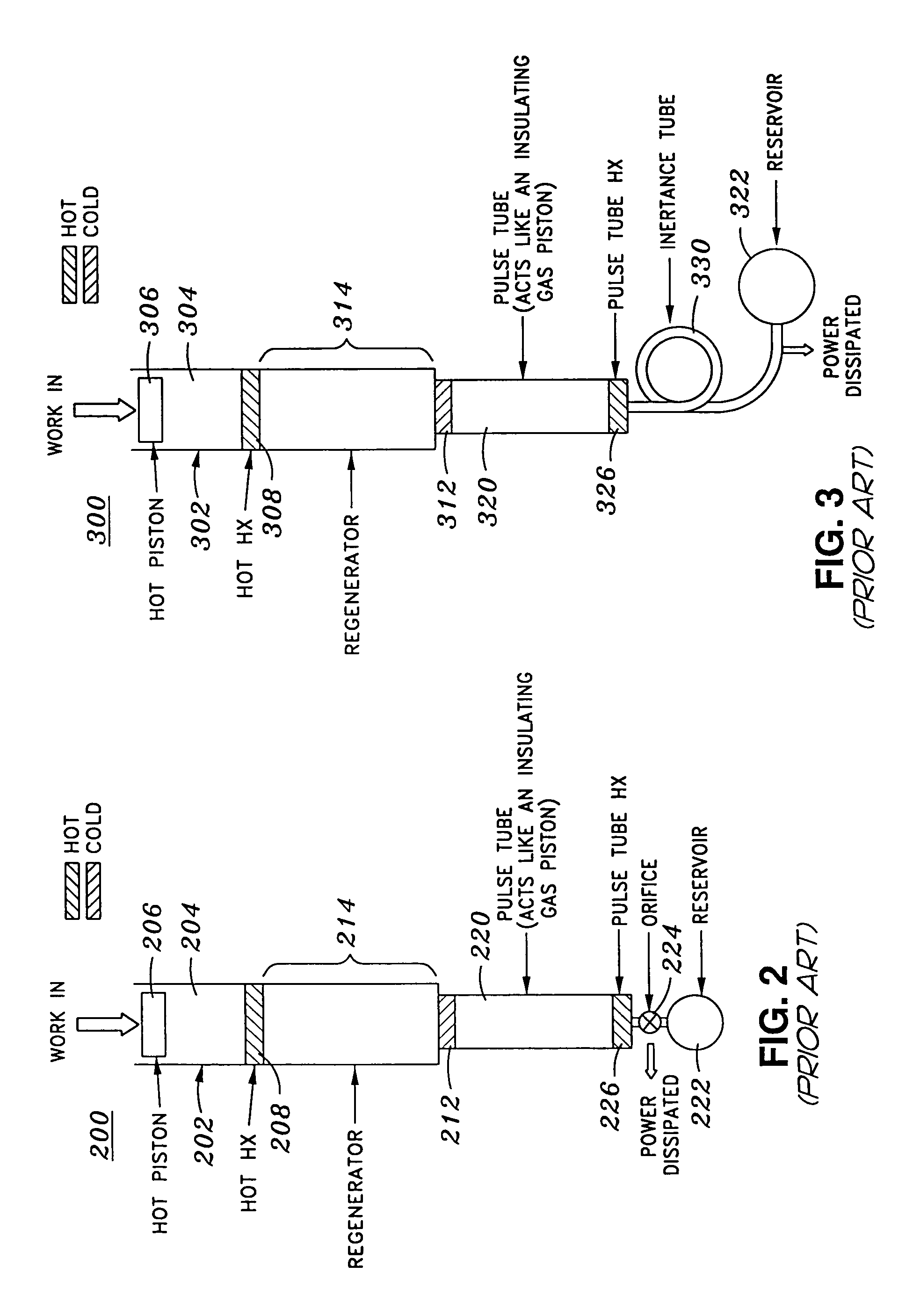
[0031]FIG. 3 shows a simplified cross-sectional view of a conventional inertance tube cryocooler structure. The inertance tube cryocooler structure 300 of FIG. 3 combines the desirable phase relationship between gas velocity and gas pressure exhibited by the Stirling cryocooler design of FIGS. 1–1D, with the reduced number of moving parts characteristic of the pulse tube cryocooler design of FIG. 2.

[0032]Specifically, like the pulse tube cryocooler shown in FIG. 2, inertance pulse tube cryocooler 300 of FIG. 3 includes tube 302 enclosing compressible gas 304 in contact with a moveable piston 306 and first heat exchanger 308 proximate to the compressible gas. Also like the pulse tube cryocooler shown in FIG. 2, the inertance tube cryocooler of FIG. 3 includes thermal regenerator 314 in contact with the compressible gas at a point between first heat exchanger 308 and second heat exchanger 312 that is in contact with the compressible gas at a point distal from first heat exchanger 308....


PUM


Abstract

The performance of a multi-stage inertance pulse tube cryocooler in accordance with an embodiment of the present invention may be enhanced by cooling the inertance tube of one stage placing it in thermal communication with the cool heat exchanger of a preceding stage. Cooling at least one inertance tube of a multi-stage cooler in this invention lowers the viscosity and sound speed of the gas in the inertance tube, thereby improving the cooling power for that subsequent cooling stage, and for the entire device.

Description

CROSS-REFERENCES TO RELATED APPLICATIONS[0001]This is a continuation application of application Ser. No. 10 / 388,187, filed Mar. 12, 2003, now U.S. Pat. No. 6,865,894, which in turn claims the benefit of U.S. Provisional Application No. 60 / 367,782, filed Mar. 28, 2002, which is incorporated by reference herein for all purposes.BACKGROUND OF THE INVENTION[0002]Cooling structures find use in a variety of applications. One class of cooling structures utilizes the compression, translation, and subsequent expansion of a gas to provide cooling effects.[0003]FIGS. 1–1D show simplified cross-sectional views of a conventional Stirling cryocooler apparatus. FIG. 1 shows the basic Stirling cooler structure 1, wherein tube 2 contains a compressible gas 4 positioned between two moveable pistons 6 and 8. A first heat exchanger structure 10 is positioned in contact with the gas proximate to first piston 6. A second heat exchanger structure 12 is positioned in contact with the gas proximate to secon...

Claims


Application Information

Patent Timeline
Patent Type & Authority Patents(United States)
IPC IPC(8): F25B9/00F25B9/10F25B9/14
CPCF25B9/145F25B9/10F25B2309/14241F25B2309/1417F25B2309/1423F25B2309/1403
Inventor OLSON, JEFFREY R.
Owner LOCKHEED MARTIN CORP
Why Eureka
Try Eureka