Thermal compensation of waveguides by dual material core having positive thermo-optic coefficient inner core

a waveguide and thermo-optic coefficient technology, applied in the field of optical circuits, can solve the problems of large power consumption, less than ideal configuration, and large size of the device formed by optical fibers

Inactive Publication Date: 2006-01-17
INTEL CORP
View PDF18 Cites 18 Cited by
  • Summary
  • Abstract
  • Description
  • Claims
  • Application Information

AI Technical Summary

Problems solved by technology

Such devices formed with optical fibers would typically be much larger or would not be feasible at all.
However, these configurations may be less than ideal, since the devices are prone to failure if there is a power outage, and temperature regulating equipment may require a large amount of power which may not be desirable.

Method used


Image

  • Thermal compensation of waveguides by dual material core having positive thermo-optic coefficient inner core
  • Thermal compensation of waveguides by dual material core having positive thermo-optic coefficient inner core
  • Thermal compensation of waveguides by dual material core having positive thermo-optic coefficient inner core

Examples


Embodiment Construction

[0018]A planar lightwave circuit comprises one or more waveguides that are thermally-compensating. The thermally-compensating waveguides comprise a cladding and a core that comprises two regions running lengthwise through the core. One region has a negative thermo-optic coefficient (“TOC”); the other region has a positive TOC.

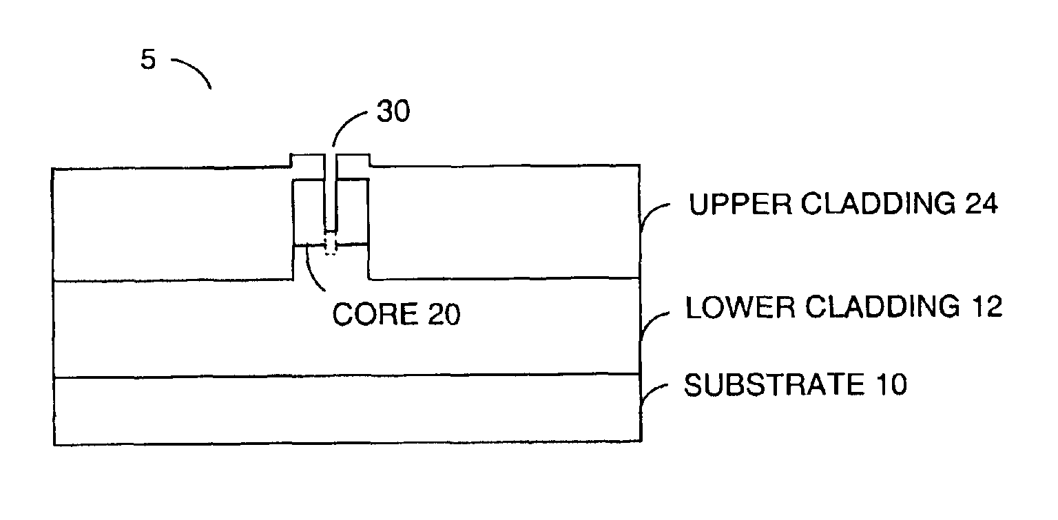
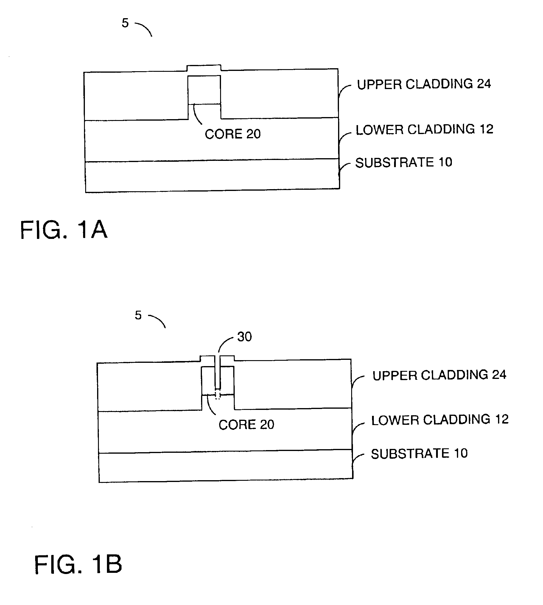
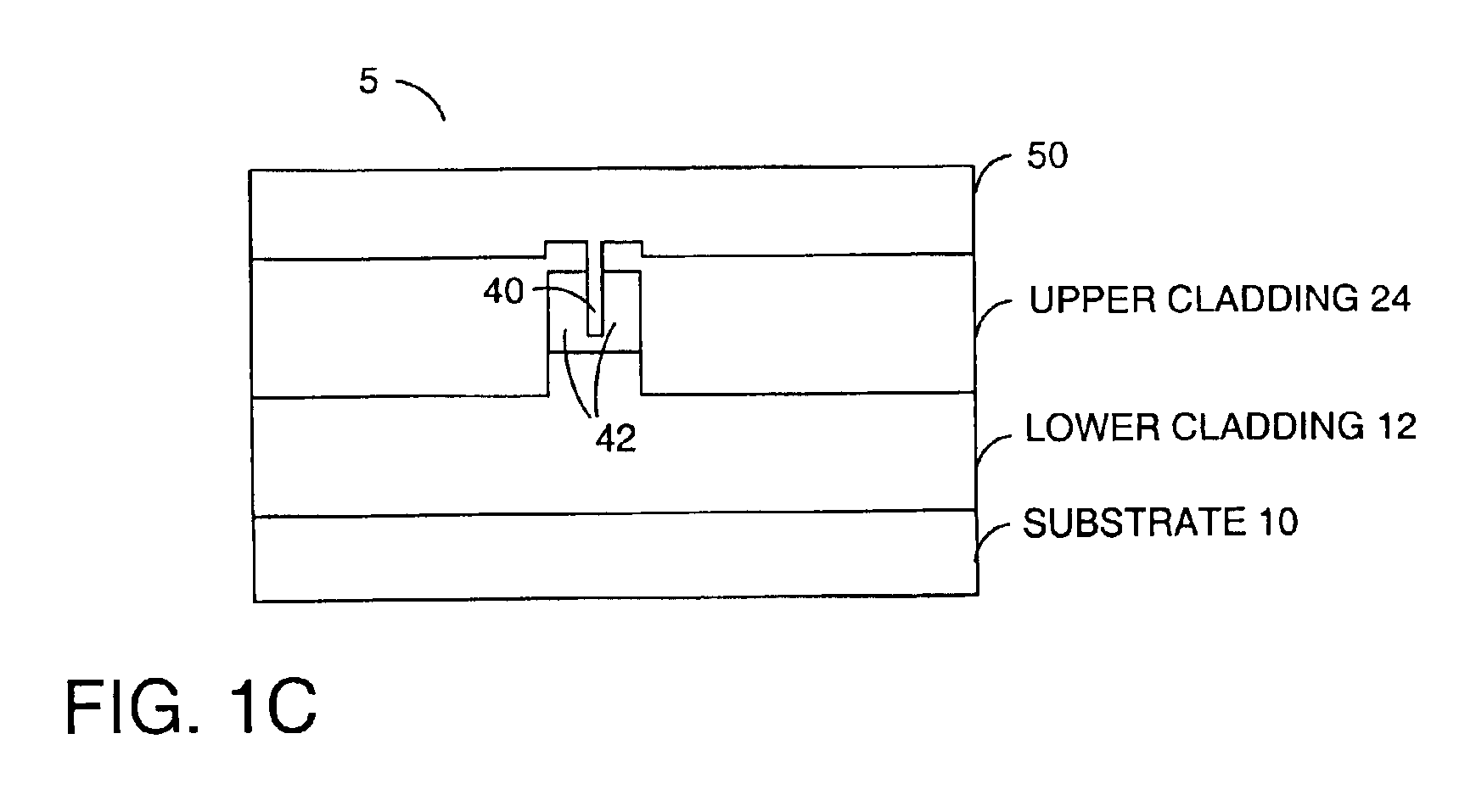
[0019]FIG. 1A is a schematic diagram showing one embodiment of a cross-sectional view of a waveguide structure 5. In one embodiment, the structure is subsequently modified as described with respect to FIGS. 1B and 1C to be thermally-compensating.

[0020]As shown in FIG. 1A, a layer of lower cladding 12 is typically deposited onto a substrate 10. A waveguide core layer 20 is deposited over the lower cladding 12, and an upper cladding 24 is deposited over the waveguide core layer 20. In one example, the substrate 10 is silicon, the lower cladding 12 is SiO2, the core layer 20 is SiO2 doped with Germanium, and the upper cladding 24 is a borophosphosilicate glass (BP...


PUM

PropertyMeasurementUnit
bend radiusaaaaaaaaaa
widthaaaaaaaaaa
lengthaaaaaaaaaa

Abstract

A planar lightwave circuit comprises a waveguide that is thermally-compensating. The waveguide comprises a cladding and a core that comprises two regions running lengthwise through the core. One region has a negative thermo-optic coefficient; the other region has a positive thermo-optic coefficient.

Description

RELATED APPLICATIONS[0001]This application is related to co-pending application, filed Jul. 2, 2002, entitled “THERMAL COMPENSATION OF WAVEGUIDES BY DUAL MATERIAL CORE HAVING NEGATIVE THERMO-OPTIC COEFFICIENT INNER CORE,” and assigned to the Assignee of the present application.BACKGROUND OF THE INVENTION[0002]1. Field of the Invention[0003]The described invention relates to the field of optical circuits. In particular, the invention relates to thermal compensation in an optical waveguide.[0004]2. Description of Related Art[0005]Optical circuits include, but are not limited to, light sources, detectors and / or waveguides that provide such functions as splitting, coupling, combining, multiplexing, demultiplexing, and switching. Planar lightwave circuits (PLCs) are optical circuits that are manufactured and operate in the plane of a wafer. PLC technology is advantageous because it can be used to form many different types of optical devices, such as array waveguide grating (AWG) filters,...

Claims


Application Information

Patent Timeline
Patent Type & Authority Patents(United States)
IPC IPC(8): G02F1/295G02B6/12G02B6/122G02F1/01
CPCG02B6/12007G02B6/1221G02B6/122
Inventor JOHANNESSEN, KJETIL
Owner INTEL CORP
Why Eureka
Try Eureka