Bicycle rack anti-sway stabilizer

a technology for bicycle racks and stabilizers, which is applied in the direction of travelling carriers, supplementary fittings, travelling articles, etc., can solve the problem of bicycle swaying sideways due to the over-the-road movement of vehicles, and achieve the effect of easy adjustment and ease of removal of pivoting stabilizers

Inactive Publication Date: 2006-01-24
NUSBAUM NEIL H +1
View PDF14 Cites 68 Cited by
  • Summary
  • Abstract
  • Description
  • Claims
  • Application Information

AI Technical Summary

Benefits of technology

[0013]An important object of the invention is the ease of removal of the pivoting stabilizer in the event small bicycles are sufficiently supported and do not require stabilization. This removal of the stabilizing member is accomplished be simply inserting an Allen wrench in the exposed head of the capscrew and rotating the screw until it is free of the threads where it may be removed with ones fingers since the nut is captured in the opposite end of the yoke.
[0014]The another rather obvious object of the invention is directed to its positive ability to prevent the bicycle mounted on the carrier rack from swaying on the carrier itself as the inertia presented by the vehicle urges the bicycle to sway angularly during stops and starts. When multiple bicycles are mounted closely together a damage potential is presented. As mentioned above the problem of misalignment is solved by the instant invention and the attachment of a strap anchor to both the top tube and either the down tube or seat tube simultaneously achieves the goal of damage prevention.
[0015]A final object of the invention is its fully adjustable nature as the anti-sway device is easily adjusted to fit almost all conventional bicycles, and the methods of attachment are intuitively obvious to the user.

Problems solved by technology

While this type of separator is well accepted and in common use, the problem of the bicycle swaying sideways due to the over the road movement of the vehicle still exists.

Method used


Image

  • Bicycle rack anti-sway stabilizer
  • Bicycle rack anti-sway stabilizer
  • Bicycle rack anti-sway stabilizer

Examples


Embodiment Construction

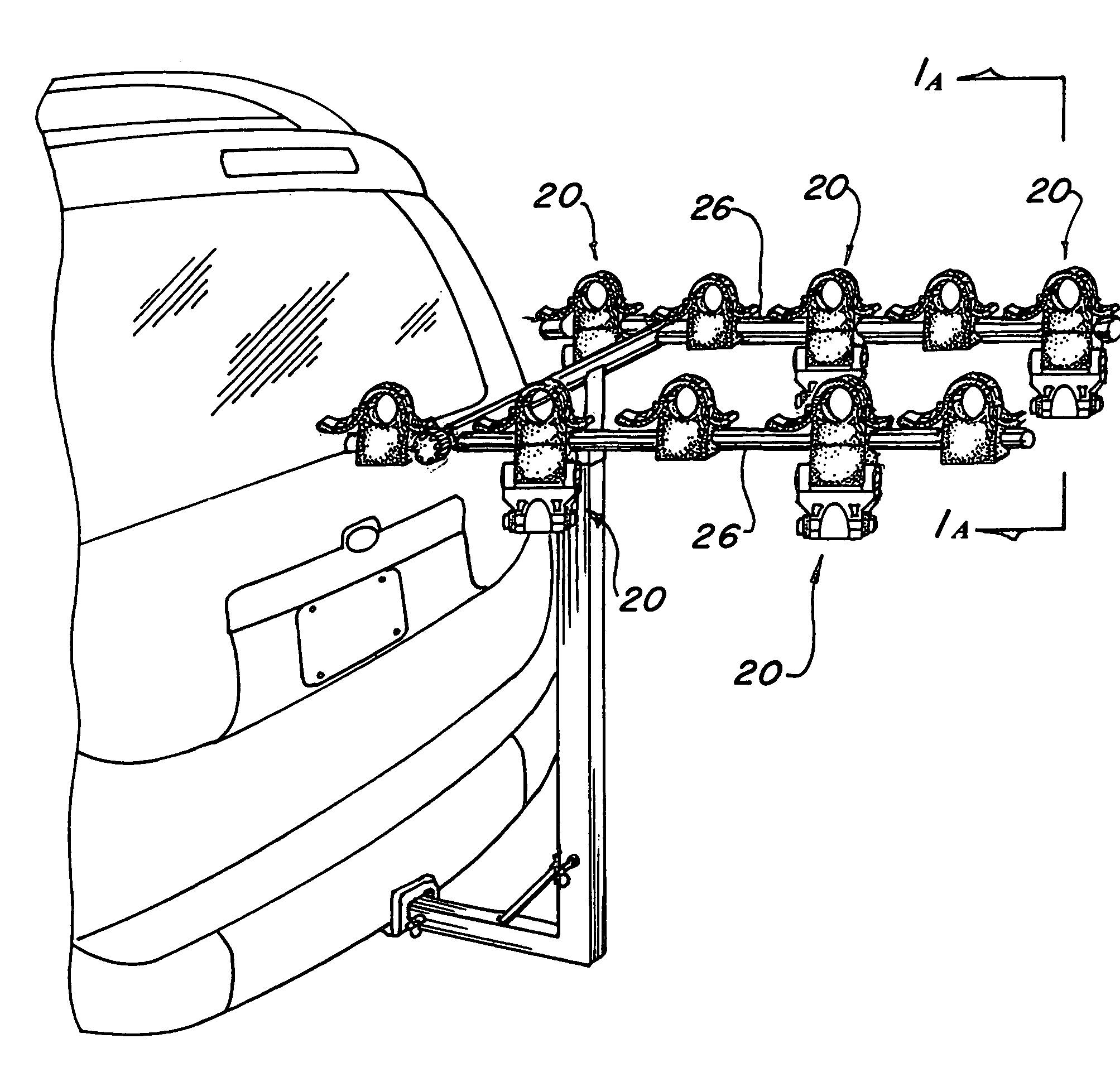
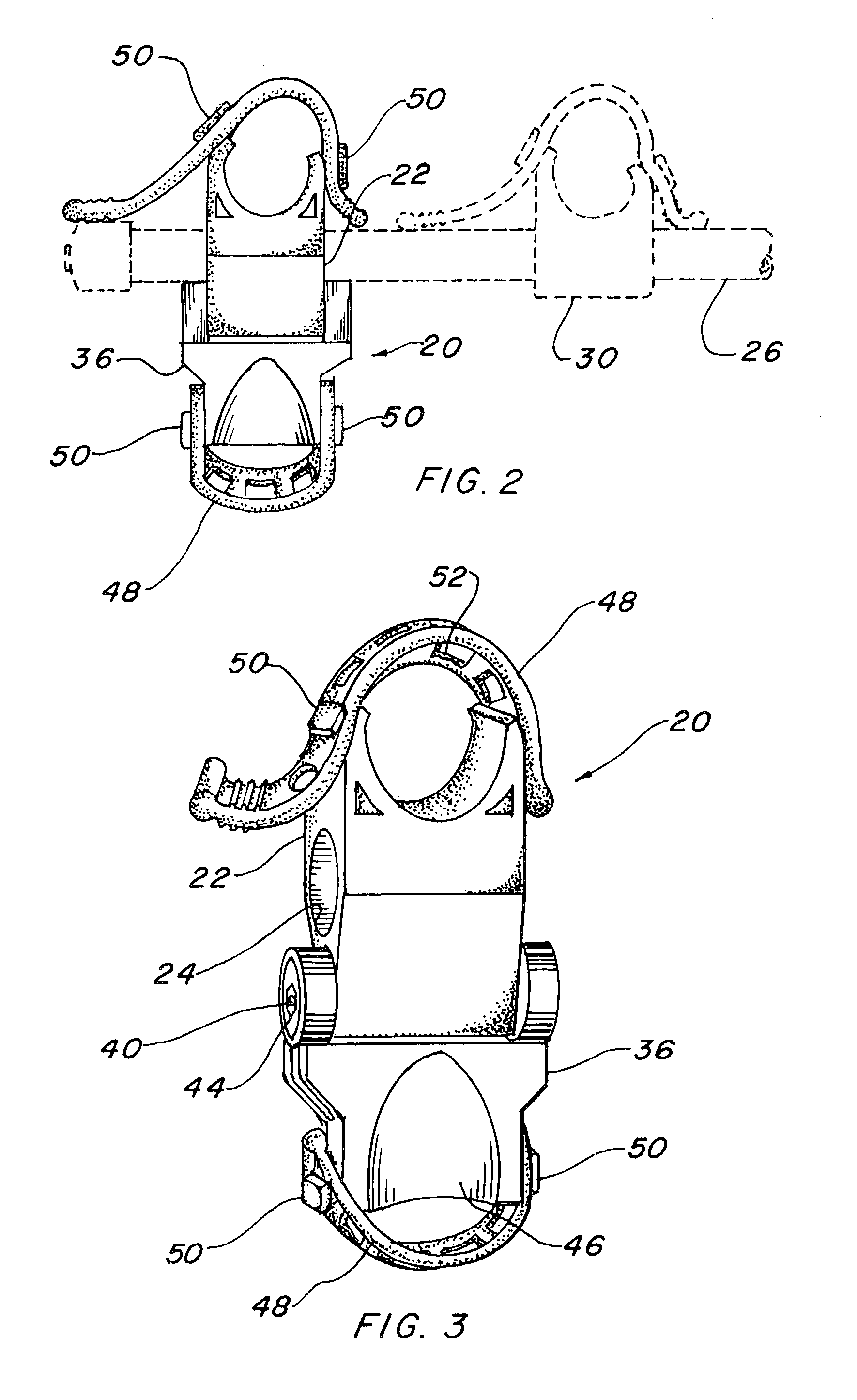
[0031]The best mode for carrying out the invention is presented in terms of a preferred embodiment. This preferred embodiment of the anti-sway stabilizer 20 is shown in FIGS. 1 thorough 12 and is comprised of two major elements.

[0032]The first element is a rubber bike separator cradle 22 that includes a bore 24 therethrougth with a size and configuration that is adaptable to slide over a vehicle bike rack support arm 26 as shown in FIGS. 1 and 2. This separator cradle is different than a conventional rubber cradle in that it is elongated and includes a thru-hole 28 that is parallel to the bore 24 as illustrated in FIGS. 3, 5–7, and 9.

[0033]The bore 24 in the bike separator cradle 22 has a smaller inside diameter than the rack support arm 26 outside diameter producing a friction fit, however, due to the elasticity of the rubber material forming the bike separator cradle 22, the cradle expands sufficiently to produce a tight grip which helps to keep the alignment of the cradle 22 on t...


PUM


Abstract

The object of the invention is to provide an anti-sway stabilizer (20) that is pivotally connected to a support arm (26) of a vehicle bike transportation rack, making available a convenient attachment of a bicycle top tube to the support arm for prevention of a bicycle held on the rack from swaying to and fro when subjected to over the road vehicle movement. The anti-sway stabilizer consists of a rubber bike separator cradle (22) that includes a bore (24) therethrougth that slides over the vehicle bike rack support arm and has a thru-hole (28) parallel with the bore. A pivoting stabilizer member (32) in the form of a yoke (36) is rotatably attached to the bike separator cradle with a screw (40) and nut (42). An attachment strap (48) secures a bicycle top tube to the bike separator cradle and a second attaching strap (48) secures a bicycle seat tube or down tube to the stabilizer member. The anti-sway stabilizer is held in place on the support arm by the combination of the separator cradle being resilient and the rigid stabilizer member contiguously engaging the support arm which precludes any lateral movement along the arm when a force is exerted in a horizontal direction biasing the anti-sway stabilizer.

Description

TECHNICAL FIELD[0001]The present invention relates to anti-sway devices in general. More specifically to an anti-sway stabilizer that is pivotally attached to rubber bike separator that is strapped onto a bicycle top tube along with either a seat tube or down tube.BACKGROUND ART[0002]Previously, many types of anti-sway stabilizers have been used in endeavoring to provide an effective means to prevent a bicycle held on a vehicle bike transportation rack from swaying sideways due to the over the road movement of the vehicle. In most cases the prior art uses a stabilizer that is pivotally mounted on the arm of the bicycle rack or is integrated into the device itself.[0003]The prior art listed below did not disclose patents that possess any of the novelty of the instant invention; however the following U.S. patents are considered related:[0004]U.S. Pat. No.InventorIssue Date4,856,686WorkentineAug. 15, 19895,259,542Newbold et al.Nov. 9, 19935,775,555Bloemer et al.Jul. 7, 19986,286,738Rob...

Claims


Application Information

Patent Timeline
Patent Type & Authority Patents(United States)
IPC IPC(8): B60R11/00
CPCB60R9/048B60R9/10B60R9/06Y10S224/924
Inventor NUSBAUM, NEIL H.LEVY, F. ANDRE
Owner NUSBAUM NEIL H
Why Eureka
Try Eureka