Push release loop

a technology of push release and loop, which is applied in the direction of marine propulsion, special-purpose vessels, vessel construction, etc., can solve the problem that no prior art address the need for a self-orienting loop, and achieve the effect of facilitating rapid deployment of the system

Active Publication Date: 2006-01-24
NALU KAI
View PDF4 Cites 42 Cited by
  • Summary
  • Abstract
  • Description
  • Claims
  • Application Information

AI Technical Summary

Benefits of technology

[0032]According to the broadest aspect of the invention, the push release loop provides an easy and reliable deployment mechanism designed to open the loop while under load in a manner in which the end result is the user being quickly and easily released from the pull of the kite, and avoids accidental opening. The direction of motion needed to activate the quick release mechanism is ideally limited to a specific direction, preferably outwardly towards the kite.
[0033]The push release loop as embodied in this invention and detailed in the attached illustrations labeled FIG. 11 performs in several novel ways. The push release loop uses a flexible plastic “sleeve” that secures the opening mechanism in the closed position. The flexible nature of this sleeve provides the right amount of resistance when activating the release mechanism. This sleeve must be moved outwardly along the rope (towards the kite or kitewardly) to open the loop and release the kite. This eliminates an external “handle” and eliminates inadvertent deployment resulting from passing water pressure or the handle becoming snagged on other gear. The mechanism also can be activated merely by pushing, which may be much easier than pulling, especially if the user's hands are cold, wet, slippery, or stiff, or if the user is injured. The mechanism ONLY works when pushed outwardly towards the kite, which is a novel and important feature.
[0035]The “sleeve”107 is equally accessible by both left and right-handed users. It is also reliably in the same place each time it needs to be activated. In order to activate the release mechanism, one only needs to slide a hand down the trim line 105 until the body of the loop is found. Grasping anywhere except for part 111 and pushing outwardly towards the kite will open the loop. This feature facilitates quick deployment of the system, which is critical in an emergency situation. The ambidextrous nature of the “trigger” is an important and novel feature of this invention.

Problems solved by technology

In addition, none of the prior art addresses the need for a self-orienting loop, and many do not remain rigid for easy engagement with the hook.

Method used


Image

  • Push release loop
  • Push release loop
  • Push release loop

Examples


Embodiment Construction

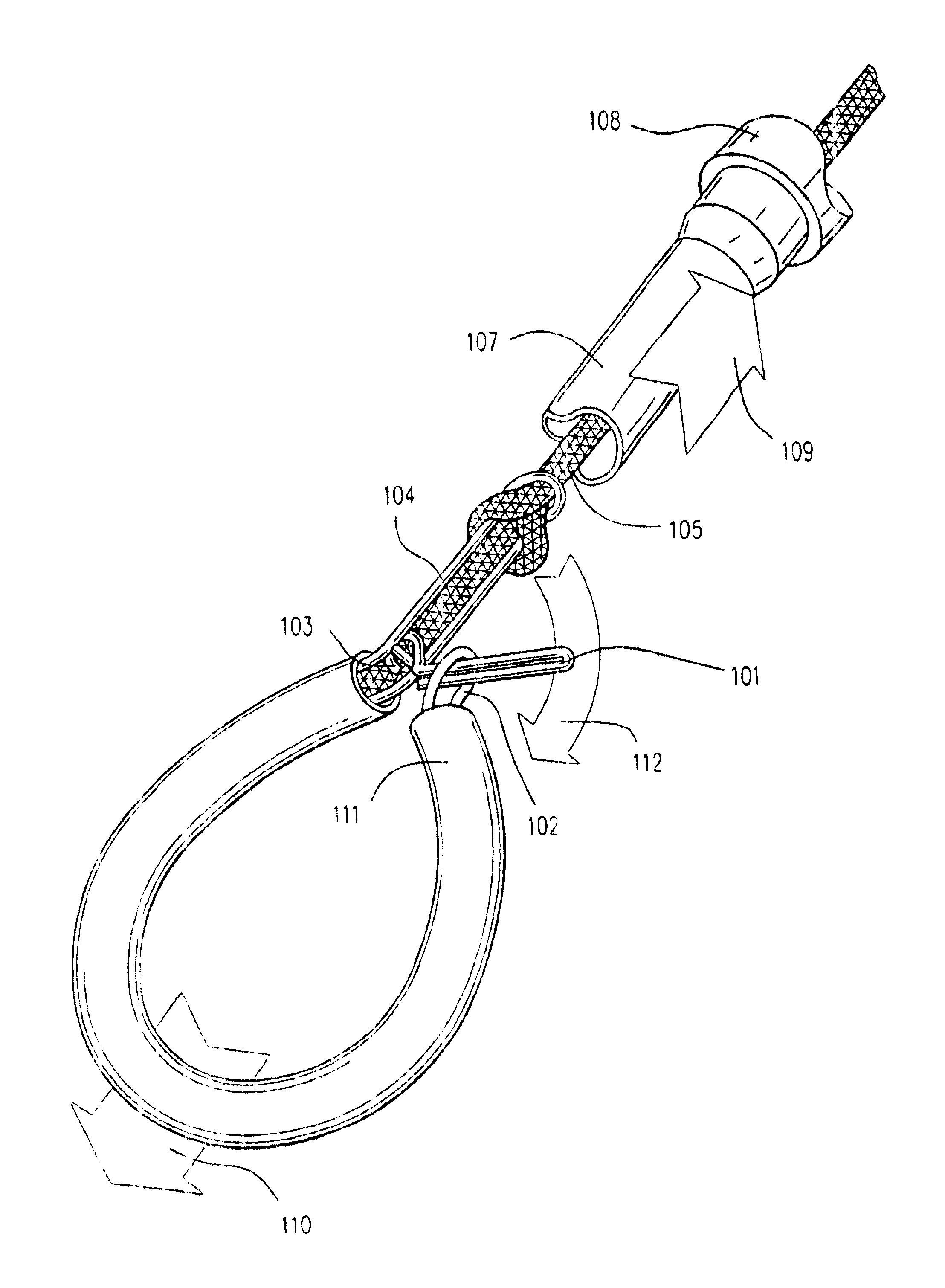
[0054]The invention is a device that push releasably retains a user end of a rope abutting against an intermediate part of the rope to form a push releasable loop. Referring to FIG. 11, a frame 104, preferably metal, is attached to an intermediate portion of the rope (preferably by intertwining) and provides a pivot point 103 for the pivot pin 101 to pivot about. The retainer 107 has a cross section larger than the cross section of the frame 104 and the pivot pin 101 when in the closed position, so that the retainer 107 can slip over the frame 104 and the closed pivot pin 101, thereby retaining the pivot pin 101 in the closed position when the retainer 107 is slid over the frame 104 and the pivot pin 101. A metal ring 102 is attached to the user end of the rope. Optionally, tubing 111 encases the loop. The distal end of the rope 105 is preferably secured to the bottom of the conventional adjuster strap.

[0055]If the retainer 107 is pushed outwardly beyond the pivot pin 101, then the ...


PUM


Abstract

The invention is a device that push releasably retains one end of a rope (111) abutting against an intermediate part of the rope (103) to form a push releasable loop.

Description

[0001]This application claims the benefit of Provisional Application No. 60 / 380,777, filed May 14, 2002.TECHNICAL FIELD[0002]Kitesurfing is a recreational activity in which the user employs a large kite to harness the wind in order to pull him / herself across the surface of the water / snow while riding on a board or other device. It is fair to think of this sport as basically water skiing behind a powerful kite, although this sport has been adapted to be used on snow / ice as well. The most popular type of kite is the inflatable kite. The kite structure consists of a framework of inflated tubes that give the kite its structure (See FIG. 1). A canopy skin is then attached to the inflated structure. This structure allows the kite to relaunch off of the water's surface, and maintains the proper shape of the kite in the air. Ram air kites are the other type of kite and are similar to the rectangular parachutes that employ a series of cells filled with air (not under high pressure) as a stru...

Claims


Application Information

Patent Timeline
Patent Type & Authority Patents(United States)
IPC IPC(8): B64C31/06A63BA63H27/08B63B35/79B63H9/04F16G11/10F16G11/14
CPCB63B35/7979F16G11/14F16G11/10B64C31/06B63H8/16B63H8/18
Inventor BARRS, CHRISTOPHER CARSWELLMONTAGUE, DONALD LEWISPOUCHKAREV, ALEXANDER
Owner NALU KAI
Why Eureka
Try Eureka