
Electric sail for producing spacecraft propulsion

Active Publication Date: 2007-09-06
JANHUNEN PEKKA
View PDF16 Cites 10 Cited by
  • Summary
  • Abstract
  • Description
  • Claims
  • Application Information

AI Technical Summary

Benefits of technology

[0007] An objective of the invention is to present a practically applicable electric sail system. Another objective of the invention is to present a spacecraft propulsion subsystem that facilitates easy and reliable deployment of the electric sail. A further objective of the invention is to present a method and a system with which it is possible to steer an electric-sail-propelled spacecraft. Yet another objective of the invention is to present an electric sail system that is tolerant against micrometeors and other hazards caused by the space environment.
[0023] If the wires are electrically conductive, it is possible to keep them at a positive potential relative to the surrounding plasma by coupling them electrically to an electron gun on board the spacecraft. The positive potential of the wires causes an electrostatic Coulomb force interaction with the protons of the solar wind, which in turn transfers momentum from the solar wind to the wires and therethrough to the whole spacecraft. Drawing electrons from the wires to the spacecraft body and emitting them to space with the electron gun counteracts the effects of solar wind electrons, which would otherwise neutralise the positive potential. Many kinds of steering manoeuvrea become possible, if the rate at which electrons are drawn from each wire is controllable.

Problems solved by technology

These delta-v values are not sufficiently high for many purposes, e.g. for reaching outer solar system targets in a reasonable time.
While somewhat higher delta-v values can be generated by reducing the payload mass fraction to a minimum, for a fixed payload this means an exponential growth of the initial mass and corresponding exponential increase of the mission cost.
Although the usability of an electric sail for spacecraft propulsion has thus been theoretically shown, there are no known practical solutions that would be applicable to implement the principle on actual space missions.

Method used


Image

  • Electric sail for producing spacecraft propulsion
  • Electric sail for producing spacecraft propulsion
  • Electric sail for producing spacecraft propulsion

Examples


Embodiment Construction

Principal Configuration

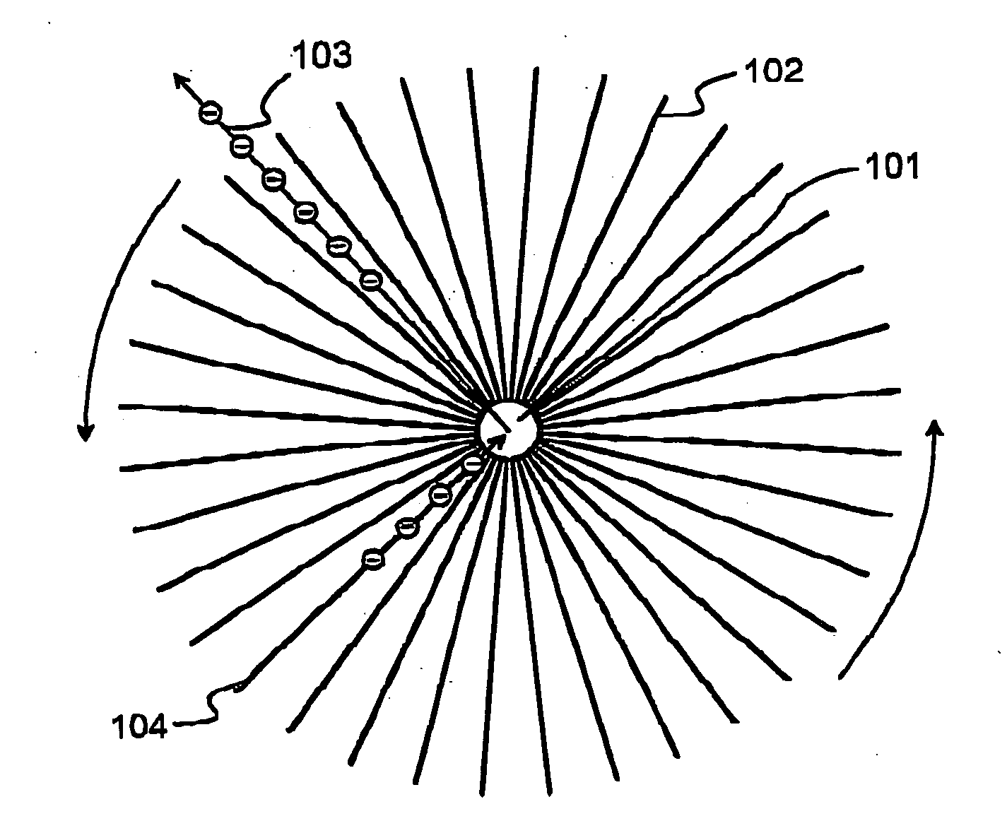
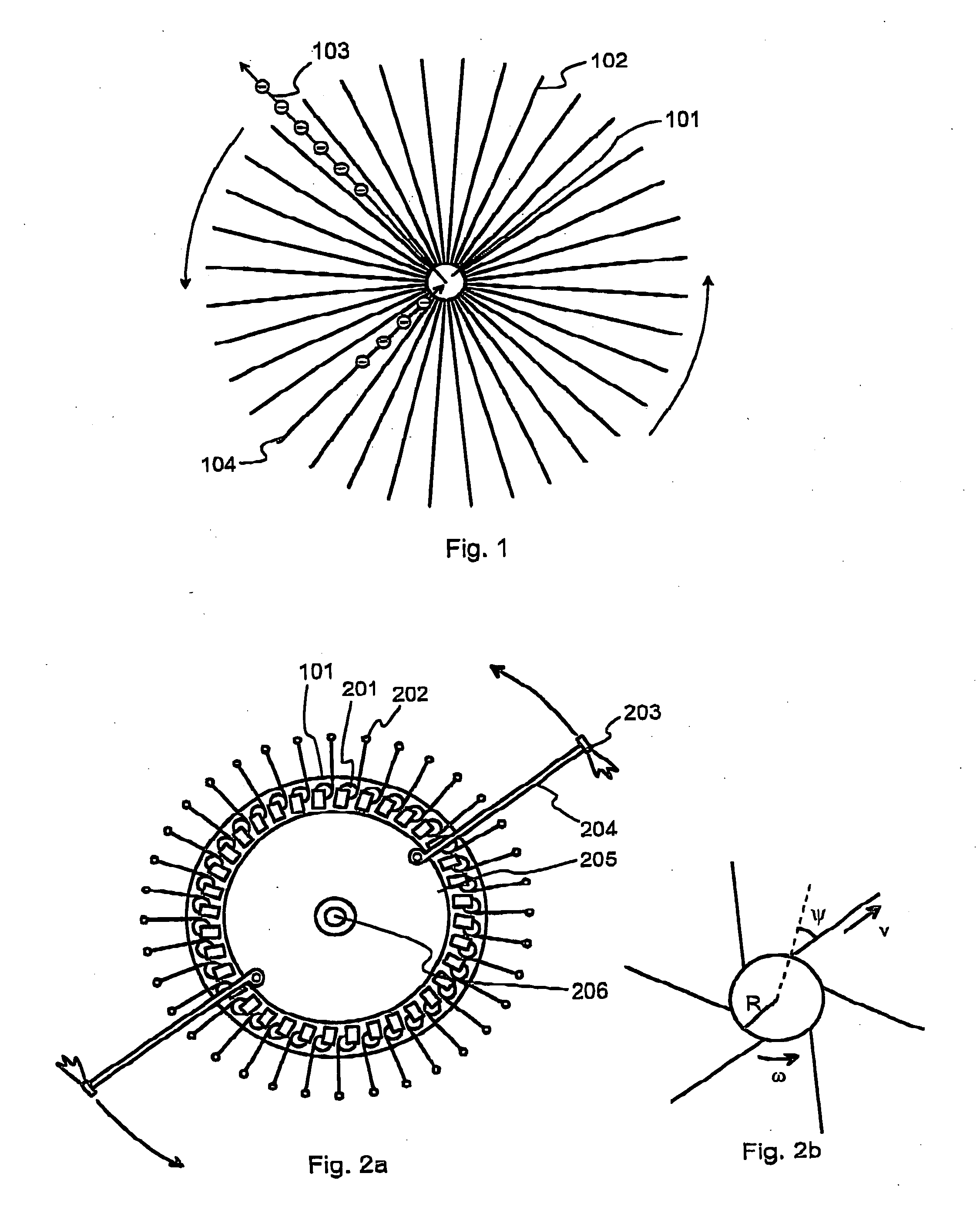
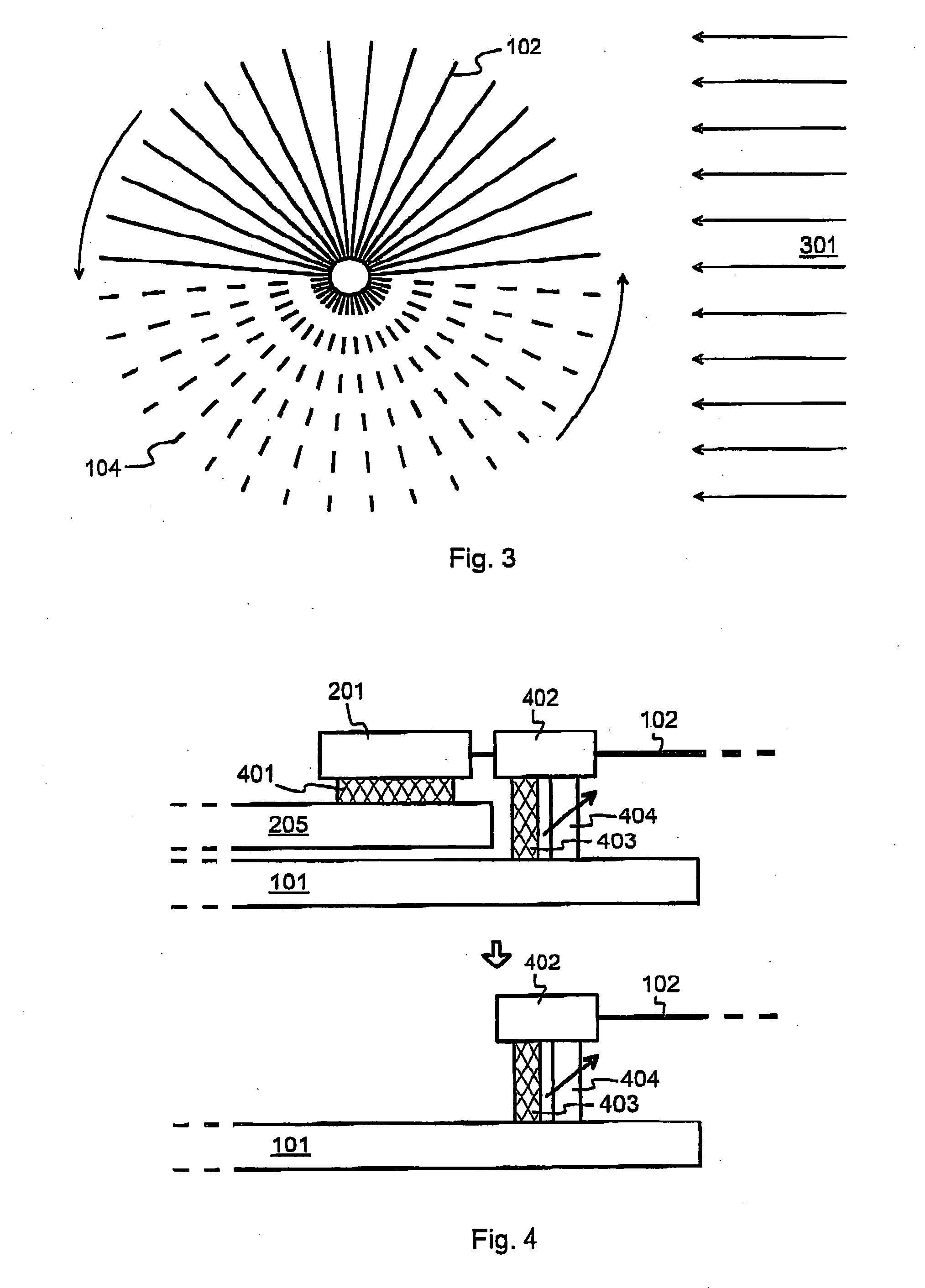
[0032]FIG. 1 illustrates schematically the basic principle of an electric sail that consists purely of radially extending wires, with no perimeter connection or other interconnections between the wires. In the middle there is the main body 101 of the spacecraft. Extending radially outwards from the main body 101, there are a number of wires, of which wire 102 is an example. The whole system rotates (spins) around a rotational axis that is perpendicular to the plane of the paper and goes through the contra of gravity of the system, which we assume to coincide with the center of the main body 101. The system is in a space environment, which means that there is essentially no similar drag caused by any surrounding medium as for example in the Earth's atmosphere. On the other hand, since each noncentrally located piece of a system rotating at constant angular velocity requires a constant centripetal force to keep It on its circular orbit, the result of the spinn...


PUM


Abstract

A spacecraft propulsion system includes a plurality of wires (102) or other electrically conductive elongated members deployed from a main body (101) into respective radial directions. An electric potential generator (605) generates an electric potential on board the main body (101). The electric coupling between the electric potential generator (605) and the elongated members is controlled (604) so that all or some of the elongated members (102) assume a high positive potential. An auxiliary propulsion system (203) rotates the main body around a rotational axis (502) that is perpendicular to the radial directions, thus creating a centrifugal supporting force to the elongated members.

Description

TECHNICAL FIELD [0001] The invention concerns generally the technology of spacecraft propulsion. Especially the invention concerns the technology of utilizing solar wind as the source of propulsive force. BACKGROUND OF THE INVENTION [0002] A spacecraft propulsion system is a subsystem of a spacecraft whose purpose is to change the state of motion of the spacecraft from its natural Keplerian motion. The Keplerian motion is due to the gravity field of the solar system bodies. Among the figures of merit of a propulsion system are the payload mass fraction and the delta-v the propulsion system can produce. Larger is better for both figures of merit. The payload mass fraction is the payload mass divided by the total initial mass (payload mass plus initial propulsion system mass) of the spacecraft. The delta-v is the time integral, computed over the working time of the propulsion system, of the non-gravitational acceleration provided by the propulsion system. [0003] Conventional propulsio...

Claims


Application Information

Patent Timeline
IPC IPC(8): B64G1/40
CPCB64G1/407B64G1/222B64G1/2225B64G1/2229
Inventor JANHUNEN, PEKKA
Owner JANHUNEN PEKKA
Learn More