Supercharge Your Innovation With Domain-Expert AI Agents!

Apparatus for delivering ablation fluid to treat lesions

a technology for ablation fluid and surgical equipment, applied in the field of surgical equipment for treating lesions, can solve the problems of insufficient ablation of cancerous tissue by rf energy application, adverse psychological impact on the patient whose treatment is being carried out, and adds to the cost of the procedur

Inactive Publication Date: 2006-01-24
REX MEDICAL LP
View PDF89 Cites 49 Cited by
  • Summary
  • Abstract
  • Description
  • Claims
  • Application Information

AI Technical Summary

Problems solved by technology

It has been documented in the literature however that RF energy application is not consistently sufficient to ablate the cancerous tissue.
This not only adds to the expense of the procedure but can have an adverse psychological impact on the patient whose treatment is prolonged and characterized by frequent hospital visits.
In additional to the clinical disadvantage, utilization of RF energy can be expensive since capital equipment, i.e. an RF generator for applying and controlling the electrosurgical energy, is required.

Method used


Image

  • Apparatus for delivering ablation fluid to treat lesions
  • Apparatus for delivering ablation fluid to treat lesions
  • Apparatus for delivering ablation fluid to treat lesions

Examples


first embodiment

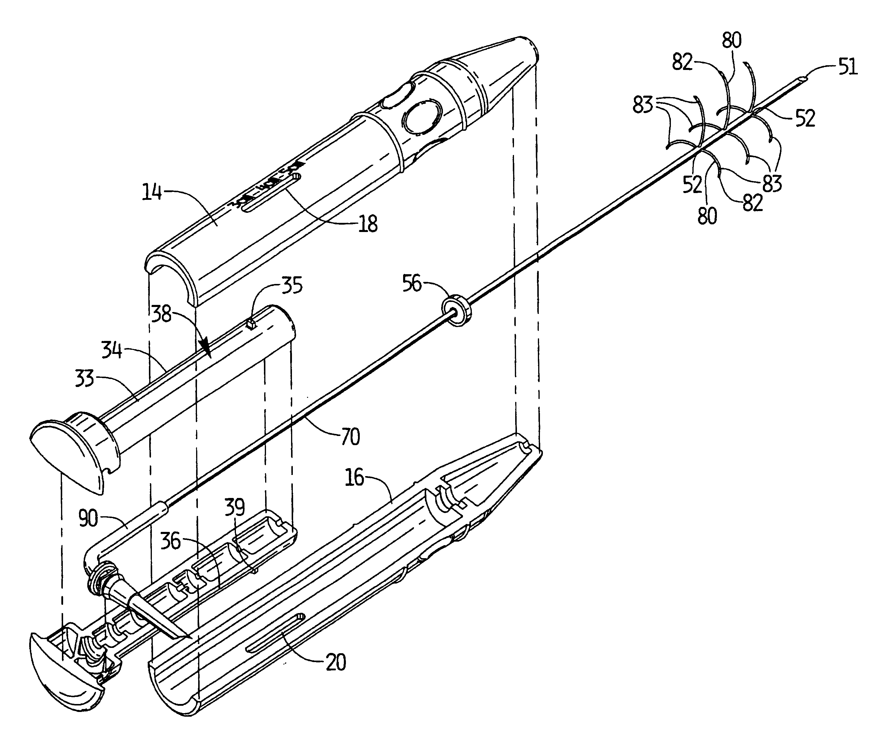
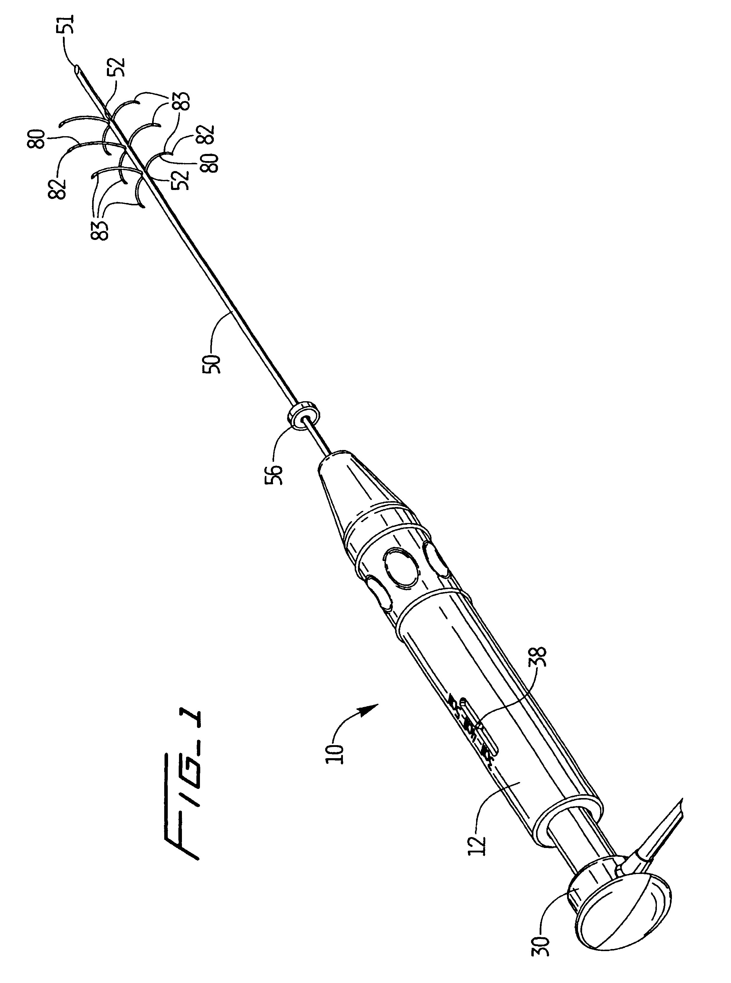
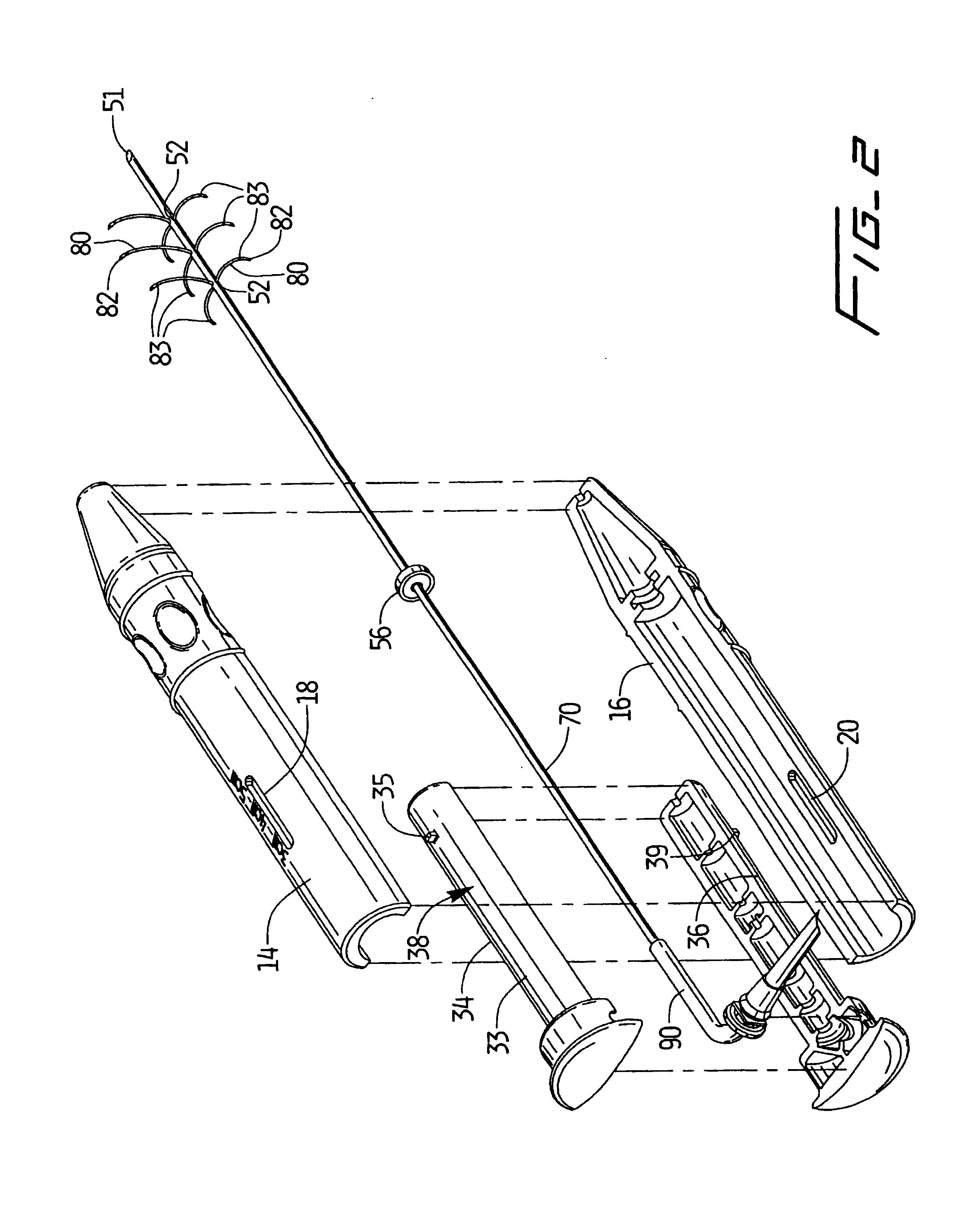
[0043]Referring now in detail to the drawings where like reference numerals identify similar or like components throughout the several views, the apparatus of the present invention for delivering fluid for tumor ablation is designated generally by reference numeral 10 and illustrated in FIG. 1. Apparatus 10 includes a housing or body 12, an actuator or plunger 30, and an elongated tubular member or needle 50 extending distally from the housing 12. A plurality of fluid delivery members or tines 80 (only a few are labeled for clarity) are extendable from the needle 50, in response to movement of the plunger 30, to deliver acetic acid, ethanol, or other ablation fluid to the target tissue. The tines 80 extend through respective side windows (openings) 52 formed in the needle 50, and each tine 80 contains openings 83 in the sidewall communicating with a lumen formed therein. The side windows 52 in needle 50 extend axially along a portion of the length of the needle 50 to enable simultan...

second embodiment

[0054]FIGS. 6-12 illustrate the fluid delivery apparatus of the present invention, designated generally by reference numeral 110. Apparatus 110 includes a housing or body 112, an actuator or plunger 130, and an elongated tubular member or needle 150 extending distally from the housing 112 through distal opening 125. The three fluid delivery tines 180a, 180b and 180c are extendable from the needle 150 through any of the three sets of windows in response to movement of the plunger 130. The tines 180, like tines 80 described above, contain openings for delivery of acetic acid, ethanol, or other ablation fluid to the target tissue. The tines 180 are also shown deployed to a position wherein their distal ends remain proximal of the distal tip 151 of the needle 150, thereby controlling the zone of acetic acid (or other ablation fluid) delivery and thus the zone of tissue ablation.

[0055]More specifically, needle 150 has three sets of windows (openings) 152, 153, and 154 forming exit apertu...


PUM


Abstract

A surgical apparatus for delivering fluid to treat a lesion comprising an elongated member having a distal tip and a first and second set of openings formed in a sidewall proximal of the distal tip. The second set of openings is positioned proximally of the first set of openings. First and second set of fluid delivery members are movably positioned in the elongated for delivering fluid to the lesion. An actuator moves the fluid delivery members from a retracted position within the elongated members to a first deployed position extending radially with respect to the elongated member and moves the fluid delivery members from the first deployed position to a second deployed position extending further radially from the elongated member. The fluid delivery members are retained in the first and second deployed positions by a retention member.

Description

[0001]This application is a continuation-in-part of application Ser. No. 10 / 081,695, filed Feb. 22, 2002, which claims priority from provisional patent application Ser. No. 60 / 348,301, filed Nov. 7, 2001 and from provisional patent application Ser. No. 60 / 272,119 filed Feb. 28, 2001, and is a continuation-in-part of application Ser. No. 10 / 074,468, filed Feb. 12, 2002, which claims priority from provisional application No. 60 / 272,119, filed Feb. 28, 2001. The entire contents of each of these applications are incorporated herein by reference.BACKGROUND[0002]1. Technical Field[0003]This application relates to a surgical apparatus for treating lesions and more particularly to an apparatus that delivers ablation fluid such as acetic acid or ethanol to ablate lesions.[0004]2. Background of Related Art[0005]One current method of treating hepatic (liver) cellular carcinomas is using electrosurgical energy in the form of radiofrequency energy. A series of electrodes are placed in the malign...

Claims


Application Information

Patent Timeline
IPC IPC(8): A61M5/178A61B17/00A61B18/00A61B19/00A61M25/00
CPCA61B18/00A61B2017/00867A61M2025/0096A61M25/0068A61M2025/0087A61B2019/5437A61B2090/3937
Inventor HINCHLIFFE, PETER W. J.MCGUCKIN, JR., JAMES F.DEFONZO, STEPHAN A.
Owner REX MEDICAL LP
Features
  • R&D
  • Intellectual Property
  • Life Sciences
  • Materials
  • Tech Scout
  • Unparalleled Data Quality
  • Higher Quality Content
  • 60% Fewer Hallucinations
Learn More