Antenna arrangement and system

a technology of antenna array and antenna array, applied in the field of antenna arrangement and system, can solve the problems of affecting the operation of different pieces of equipment, affecting the operation of hospital machines and equipment, and causing regions, so as to effectively eliminate the signal “null” region and accurately identify and inventory an identification element.

Active Publication Date: 2006-01-24
MOBILE ASPECTS INC
View PDF9 Cites 61 Cited by
  • Summary
  • Abstract
  • Description
  • Claims
  • Application Information

AI Technical Summary

Benefits of technology

[0010]It is, therefore, an object of the present invention to provide an antenna arrangement and system that overcomes the deficiencies in the prior art. It is another object of the present invention to provide an antenna arrangement and system for use in connection with an enclosure manufactured from a field-absorbing material. It is a further object of the present invention to provide an antenna arrangement and system that effectively eliminates the signal “null” region in the enclosure. It is a still further object of the present invention to provide an antenna arrangement and system that can accurately identify and inventory an identification element, such as a RF / ID tag, regardless of its position with respect to the antenna element.

Problems solved by technology

Such fields could also interfere with the operation of different pieces of equipment, such as hospital machines and equipment.
Using these field-absorbing or field-reflecting materials leads to other drawbacks.
The main drawback of using such materials is that, due to the nature of the antenna placement and the enclosure materials of construction, one and typically multiple signal “null” or “void” regions are created by the absorption.
This represents a fundamental failure in the system and represents a critical error in providing an accurate inventory system.

Method used


Image

  • Antenna arrangement and system
  • Antenna arrangement and system
  • Antenna arrangement and system

Examples


Embodiment Construction

[0023]For purposes of the description hereinafter, the terms “upper”, “lower”, “right”, “left”, “vertical”, “horizontal”, “top”, “bottom”, “lateral” and derivatives thereof shall relate to the invention as it is oriented in the drawing figures. However, it is to be understood that the invention may assume various alternative variations and step sequences, except where expressly specified to the contrary. It is also to be understood that the specific devices and processes illustrated in the attached drawings, and described in the following specification, are simply exemplary embodiments of the invention. Hence, specific dimensions and other physical characteristics related to the embodiments disclosed herein are not to be considered as limiting.

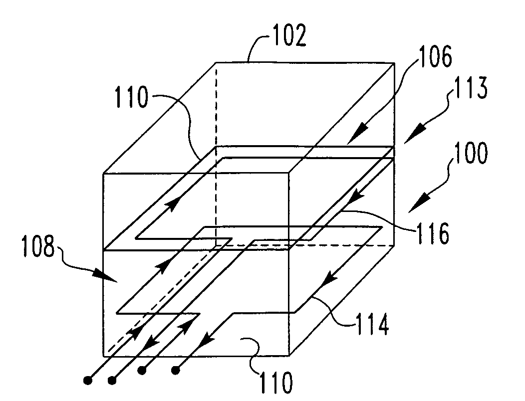
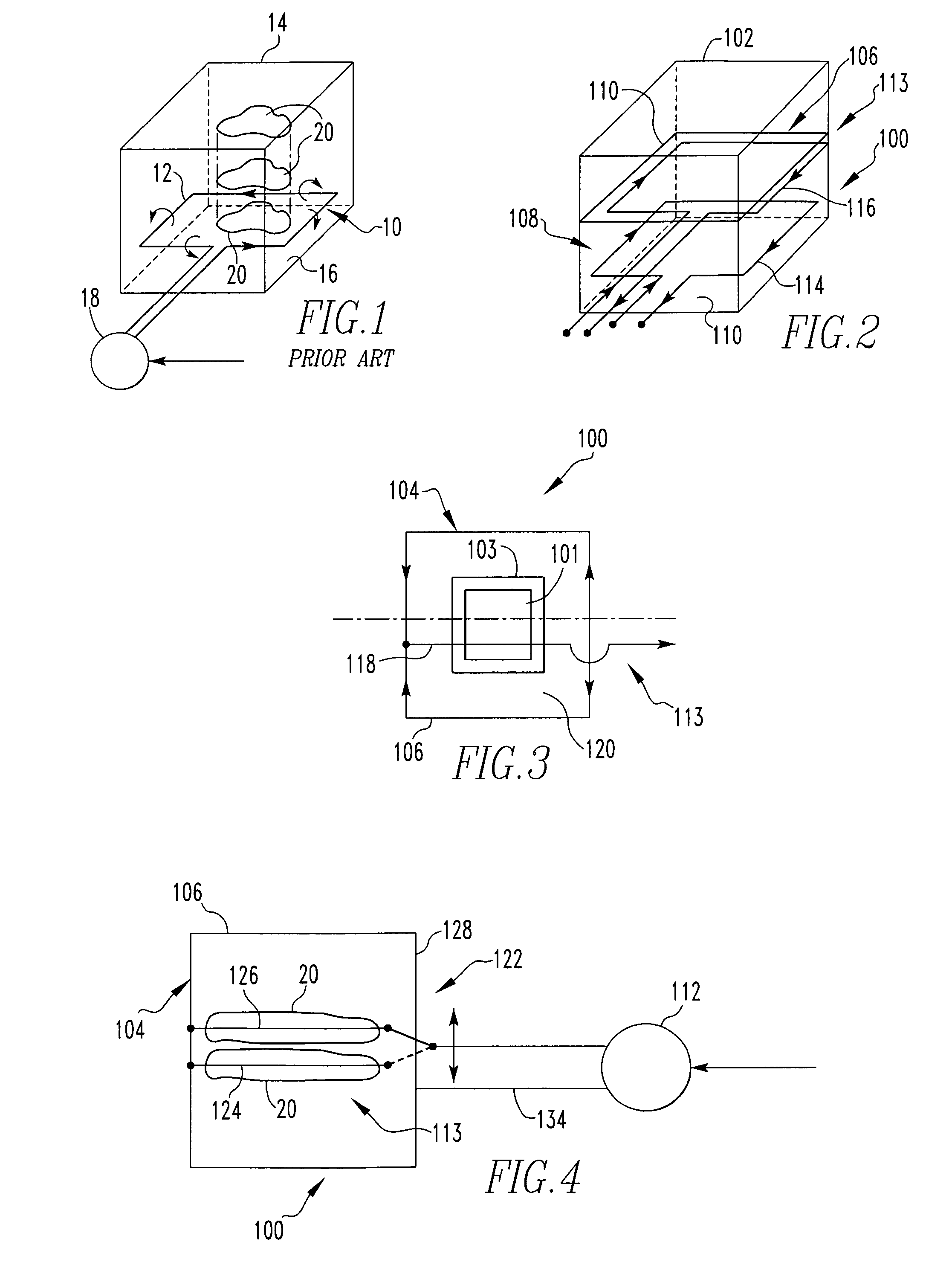
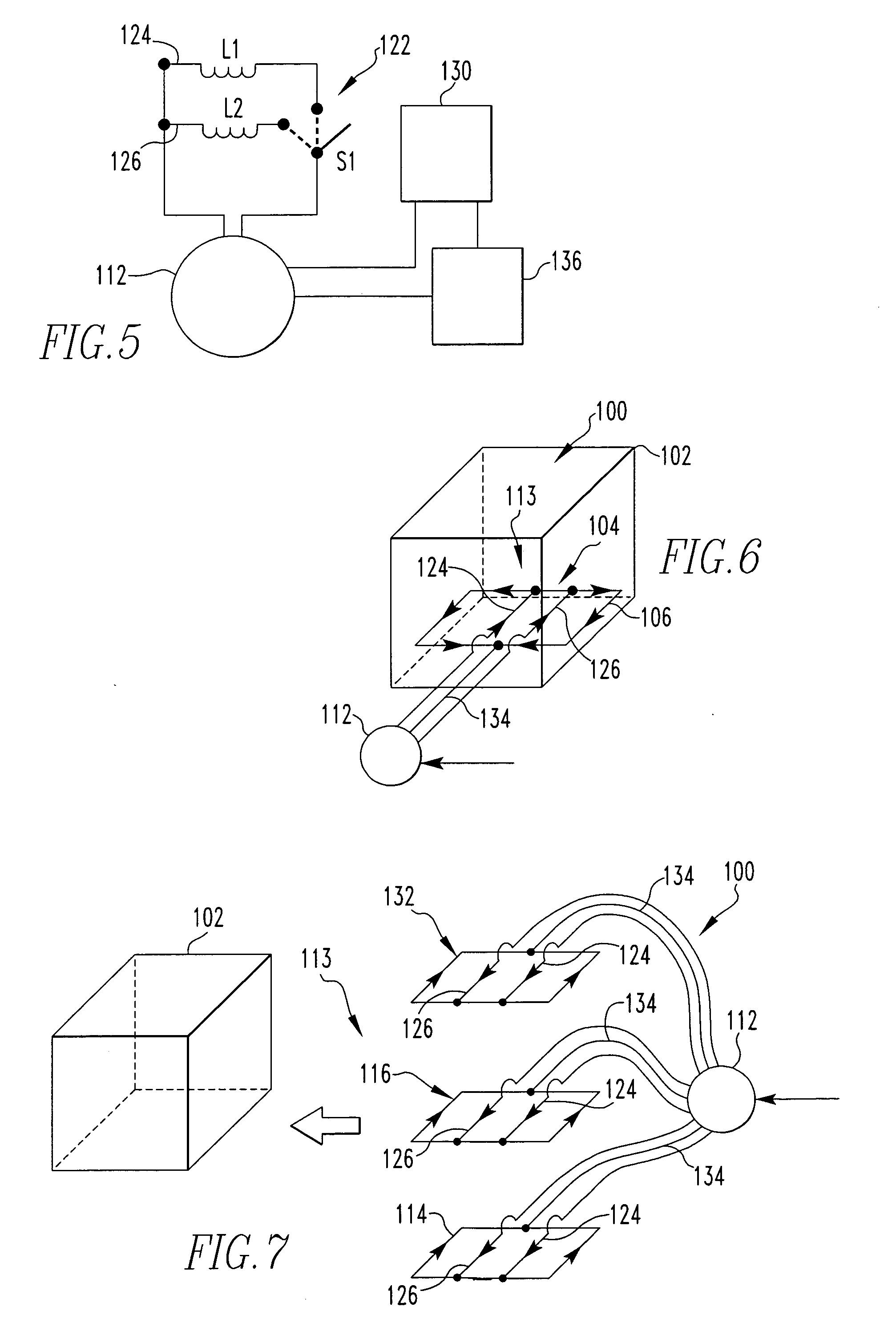
[0024]The present invention is an antenna arrangement 100 for use in connection with communicating with and identifying one or more identification elements 101, typically in the form of RF / ID tags or labels, which are, in turn, in operable com...


PUM


Abstract

An antenna arrangement for identifying an identification element in communication with an object located in an enclosure having a “null” signal region. The antenna arrangement includes a primary antenna loop element positioned in operable communication with the enclosure and the identification element positioned within the enclosure. The primary antenna loop element communicates with the identification element and receives a signal from the identification element, thereby tracking the object associated therewith. A feed point mechanism communicates with the antenna loop element and energizes the antenna loop element, transmits signals and/or receives signals. The arrangement includes a subsequent antenna element in communication with the enclosure and the identification element positioned within the enclosure, and the subsequent antenna element substantially eliminates the signal “null” region, such that at least one of the primary loop element and the subsequent antenna element can communicate with the identification element.

Description

CROSS REFERENCE TO RELATED APPLICATIONS[0001]This application claims the benefit of U.S. Provisional Patent Application No. 60 / 465,477, filed Apr. 25, 2003, which is hereby incorporated by reference in its entirety.BACKGROUND OF THE INVENTION[0002]1. Field of the Invention[0003]The present invention relates generally to antenna arrangements and systems in the field of signal identification, such as radio frequency identification (RF / ID) technology and, in particular, to an antenna arrangement and system for use in connection with enclosures manufactured from field-absorbing or field-reflecting materials, such as metals, semi-metals, etc., the enclosure having one or more signal “null” regions therein.[0004]2. Description of the Related Art[0005]Radio frequency identification (RF / ID) technology is used in many applications for both communication and identification of objects, items, inventory and the like. For example, in many inventory applications, one or more objects that a user i...

Claims


Application Information

Patent Timeline
Patent Type & Authority Patents(United States)
IPC IPC(8): H01Q11/12G06K7/08H01Q1/22H01Q3/24H01Q7/00H01Q21/06
CPCG06K7/10336H01Q1/22H01Q21/06H01Q3/24H01Q7/00H01Q1/2216
Inventor RAHIM, MUHAMMAD
Owner MOBILE ASPECTS INC
Why Eureka
Try Eureka