Polyphase-discrete fourier transform (DFT) sub-band definition filtering architecture

a fourier transform and subband definition technology, applied in frequency-division multiplexing, orthogonal multiplexing, instruments, etc., can solve the problems of increasing the coefficient and arithmetic bit width, requiring a large number, etc., and achieves less bandwidth, power saving, and power saving

Inactive Publication Date: 2006-01-24
TAMIRAS PER PTE LTD LLC
View PDF19 Cites 14 Cited by
  • Summary
  • Abstract
  • Description
  • Claims
  • Application Information

AI Technical Summary

Benefits of technology

[0026]To address applications where a large number of channels need to be multiplexed, a novel architecture has been developed that exploits the efficiency of the PPF-DFT filter bank to divide the spectrum of the signal to be demultiplexed into sub-bands. The number of sub-bands is chosen such that each contains a sufficiently small number of channels to allow the sub-band to be demultiplexed with a low order PPF-DFT filter bank. This filter bank can be implemented with smaller coefficient and arithmetic bit widths thus saving power and mass over the direct approach.
[0027]The PPF-DFT sub-band definition filtering architecture can use two identical PPF M-DFT N filter banks, with a π / N complex bandshift to divide the input signal spectrum into an integer P even and P odd sub-bands, each with a factor of 2P less bandwidth and channels to be demultiplexed. The sub-bands are demultiplexed with identical PPF-DFT filter banks, the order of which is a factor of 2P less than the order of the conventional single stage PPF-DFT filter bank demultiplexer. Moreover, the sub-band definition filtering architecture results in a tree-like structure which can be “pruned,” e.g., CMOS ASIC clock disabled, to eliminate branches containing no active channels to save power.
[0028]Advantageously, a feature of the invention can minimize power consumption in applications exhibiting active channel sparsity and critically limited power consumption constraints. As a consequence, the transition bands of the PPF-DFT filter banks can be allowed bandwidths equal to one-half of the filter banks' output sampling rate, thereby admitting very low order, hence computationally efficient, polyphase filters in the sub-band definition network implementation of the present invention.

Problems solved by technology

However, many applications require a prohibitively large number (e.g., much greater than 32) of FDMchannels to be demultiplexed.
Unfortunately, directly demultiplexing a large number of channels requires a higher order PPF-DFT filter bank, which in turn can only be implemented with higher coefficient and arithmetic bit widths.

Method used


Image

  • Polyphase-discrete fourier transform (DFT) sub-band definition filtering architecture
  • Polyphase-discrete fourier transform (DFT) sub-band definition filtering architecture
  • Polyphase-discrete fourier transform (DFT) sub-band definition filtering architecture

Examples


Embodiment Construction

[0044]A preferred embodiment of the invention is discussed in detail below. While specific exemplary implementation embodiments are discussed, it should be understood that this is done for illustration purposes only. A person skilled in the relevant art will recognize that other components and configurations may be used without parting from the spirit and scope of the invention.

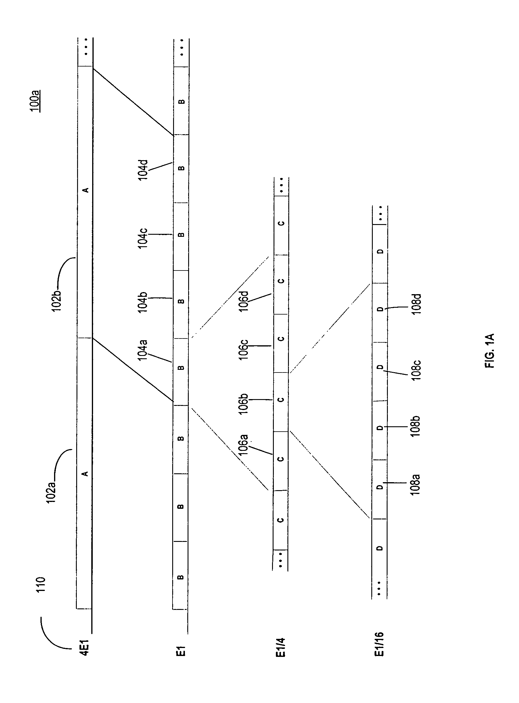
[0045]FIG. 1A depicts an exemplary embodiment of an FDM signal band 100a and exemplary nested sub-bands 102, 104, 106 and 108 according to the present invention. The A sub-bands 102a, 102b, 102c and 102d (collectively 102) can contain the widest channel with the highest power and highest rate of transmission. Each A-sub band 102a,b,c and d can contain, in an exemplary embodiment, up to four B sub-bands 104a–d. Each B sub-band 104a–d can contain up to 4 C sub-bands 106a–d. Each C sub-band 106a–d can contain up to 4 D sub-bands 108a–d. Note that if an A sub-band channel 102 is operative, none of the sub-band ch...


PUM


Abstract

A system and method for demultiplexing an RF signal including nested frequency division multiplexed (FDM) channels is disclosed. The system can demultiplex an RF signal including at least two nested sets of FDM channels extending over a bandwidth B.

Description

CROSS-REFERENCE TO RELATED APPLICATION[0001]The following application of common assignee may contain common disclosure with the present application:[0002]Provisional U.S. Patent Application Ser. No. 60 / 181,512 entitled “Polyphase-Discrete Fourier Transform (DFT) Sub-band Definition Filtering Architecture,” to Thomas C. Butash, filed Feb. 11, 2000, the contents of which are hereby incorporated by reference in their entireties.BACKGROUND OF THE INVENTION[0003]1. Field of the Invention[0004]The present invention relates generally to demultiplexing large numbers of channels, and more particularly, to demultiplexing nested sets of frequency division multiplexed (FDM) channels.[0005]2. Related Art[0006]The polyphase-discrete fourier transform (PPF-DFT) filter bank is widely recognized as the most computationally efficient means of demultiplexing a group of uniformly spaced frequency division multiplexed (FDM) channels of equal bandwidth. However, many applications require a prohibitively ...

Claims


Application Information

Patent Timeline
Patent Type & Authority Patents(United States)
IPC IPC(8): H04J11/00G06F17/14H03H17/02H04J1/05H04L5/06
CPCG06F17/141H03H17/0273H04L5/06H04J1/05H03H2218/04
Inventor BUTASH, THOMAS C.
Owner TAMIRAS PER PTE LTD LLC
Why Eureka
Try Eureka