Shower pan

a technology for showering pans and shower doors, which is applied in the field of showering pans, can solve the problems of affecting the appearance of showering pans, so as to achieve the effect of preventing water from entering the showering pans

Inactive Publication Date: 2006-01-31
GRAYSON A BRENT
View PDF13 Cites 45 Cited by
  • Summary
  • Abstract
  • Description
  • Claims
  • Application Information

AI Technical Summary

Benefits of technology

[0004]Therefore it is an object of the present invention to provide a shower pan for use in a shower stall that effectively prevents water leakage into structures outside of the shower stall.
[0006]It is yet another object of the present invention to provide a shower pan that prevents water leakage, and does not require sealant.
[0009]According to a preferred embodiment of the invention, the door track is higher than the outer ridge for allowing sufficient clearance of a shower stall door mounted on said door track to open and close over said outer ridge.

Problems solved by technology

However, such a configuration allows for water streaming through cracks in the door track on which the door is mounted to escape the shower pan and shower stall as there is no ridge or similar structure to stop the water.
Water seeping through crevices in the door track flows out of the shower stall and can damage surrounding wood structures.
Adding sealant is time consuming and not completely effective in stopping leakage.

Method used


Image

  • Shower pan
  • Shower pan
  • Shower pan

Examples


Embodiment Construction

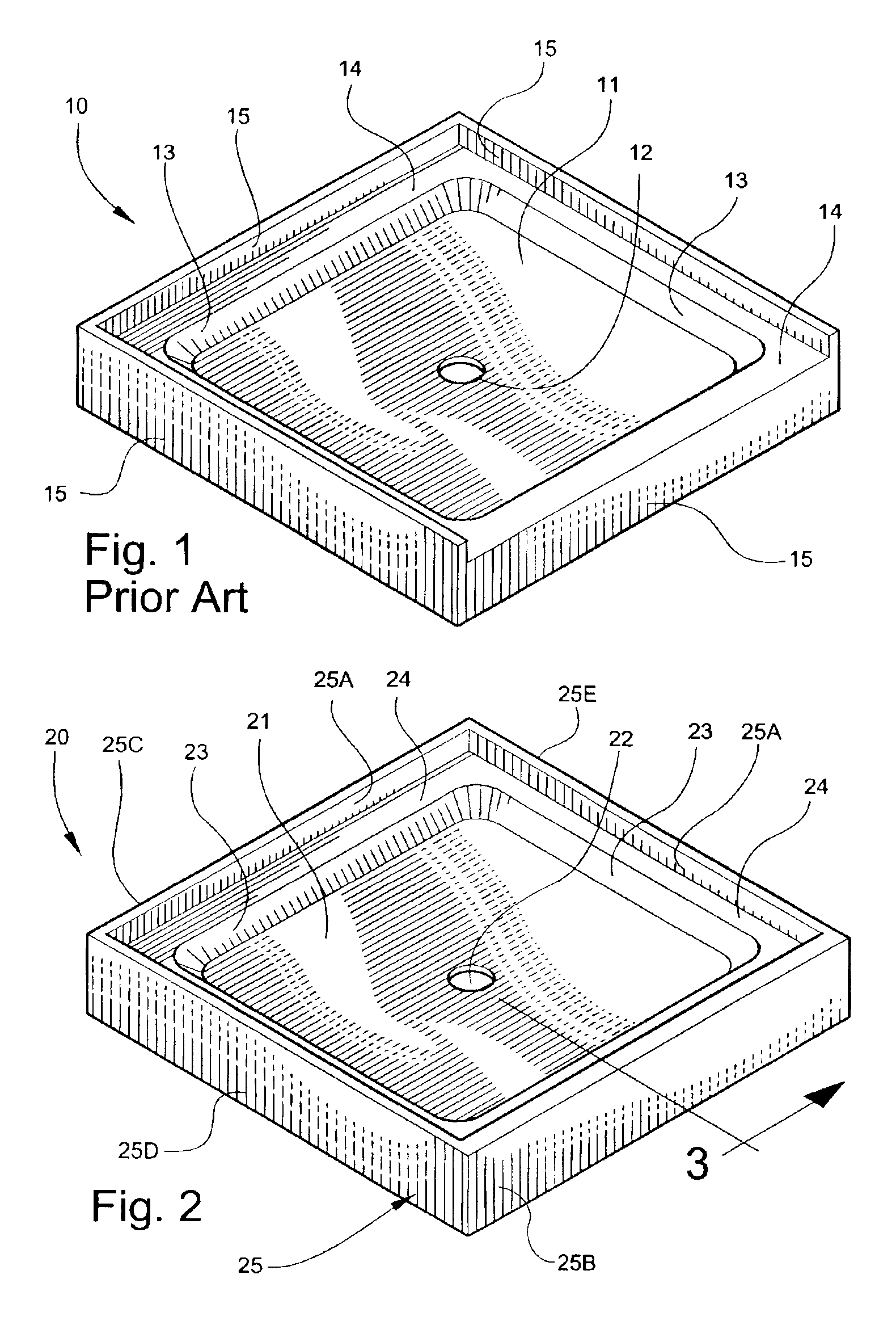
[0035]Referring now specifically to the drawings, a shower pan 10 according to the prior art is illustrated in FIG. 1, and shown generally at reference numeral 10. The prior art shower pan comprises a rectangular base 11 with a drain hole 12 located in the center of the base 11 for draining water out of a shower stall. A sidewall 13 extends upwardly from the base 11, and a lateral ledge 14 extends outwardly from the top of the sidewall 13. On three sides of the shower pan 10, an outer wall 15 extends above the outer edge of the lateral ledge 14. On one side of the shower pan, the outer wall 15 terminates at the outer edge of the lateral ledge 14.

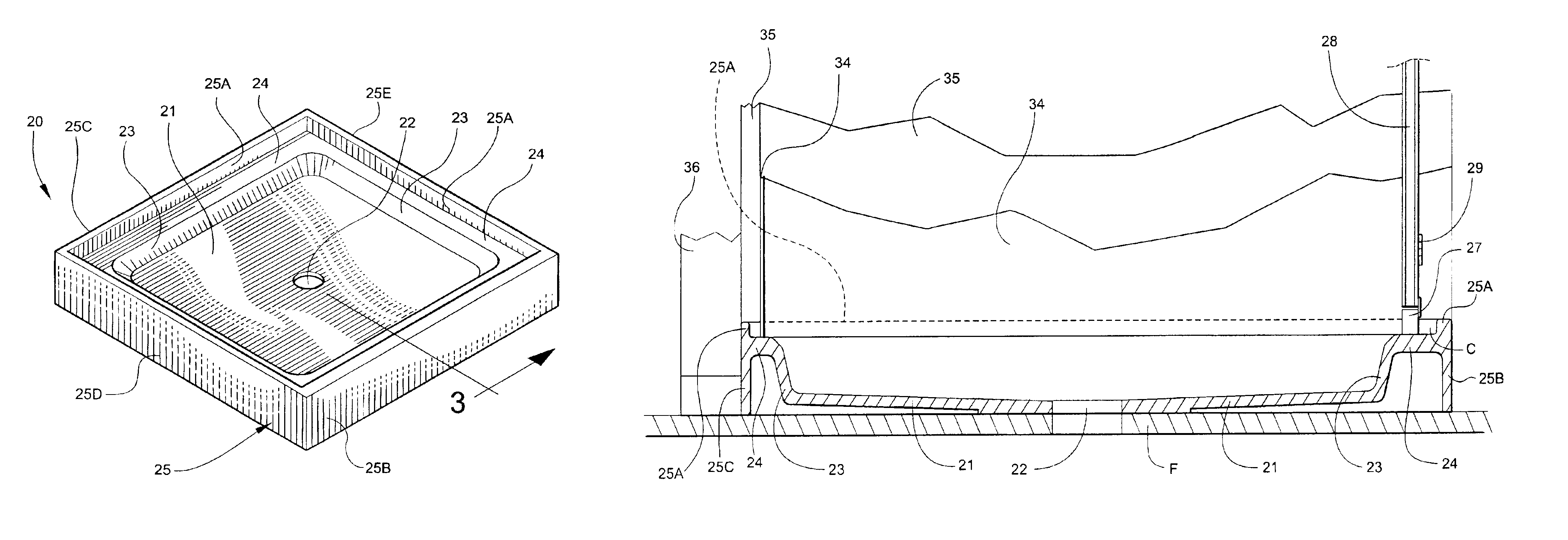
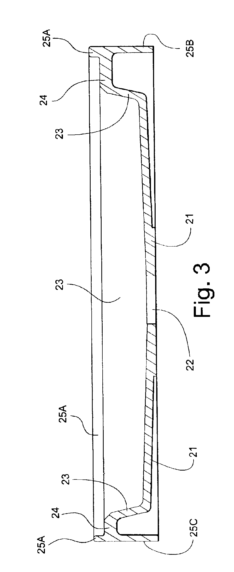
[0036]A shower pan according to a preferred embodiment of the present invention is illustrated in FIG. 2, and shown generally at reference numeral 20. The shower pan 20 comprises a rectangular base 21 having a drain hole 22 located in the center of the base 21. A sidewall 23 extends upwardly from the base 21, and a lateral ledge 24 extends o...


PUM


Abstract

A shower pan for mounting in a shower stall includes a single integrally molded base with a drain hole. A sidewall extends upwardly from the base and completely surrounds the base. A lateral ledge extends outwardly from the sidewall and has an inner edge and an outer edge defining a surface therebetween for mounting a shower stall door track. An outer ridge extends upwardly from the outer edge of the lateral ledge and is in spaced apart relation to the door track. Water flowing through cracks between the door track and the shower pan is prevented from escaping the shower pan by the outer ridge, which allows water to drain under the door track into the shower pan.

Description

TECHNICAL FIELD AND BACKGROUND OF THE INVENTION[0001]The invention relates to a shower pan for use in a shower stall. Such shower pans act as a base in the shower stall on which the user stands while showering, and includes a drain hole for allowing water to drain out of the shower stall.[0002]While shower stalls may be any shape, many are rectangular, having three shower surface walls and a fourth side on which a shower stall door is mounted. An important concern is the prevention of water leakage from the shower stall into surrounding structures outside of the shower stall. In an attempt to prevent leakage, prior art shower pans have utilized a water dam extending upward from the base of the shower pan on all four sides. On the three sides supporting the shower surface walls, a ridge extends upward from the water dam, behind the shower surface walls. The shower door is mounted on the water dam on the remaining side, which does not include a ridge, presumably to allow for the showe...

Claims


Application Information

Patent Timeline
Patent Type & Authority Patents(United States)
IPC IPC(8): A47K3/36A47K3/34A47K3/40
CPCA47K3/40
Inventor GRAYSON, A. BRENT
Owner GRAYSON A BRENT
Why Eureka
Try Eureka