Electrical connector having improved contact

a technology of electrical connectors and connector tails, applied in the direction of coupling contact members, coupling device connections, coupling/insulating coupling contact members, etc., can solve the problems of inconvenient replacement of connectors, damage to the circuit trace of printed circuit boards or the tail of contacts, waste of whole, etc., and achieves the effect of improving contact and enough flexibility

Inactive Publication Date: 2006-01-31
HON HAI PRECISION IND CO LTD
View PDF15 Cites 31 Cited by
  • Summary
  • Abstract
  • Description
  • Claims
  • Application Information

AI Technical Summary

Benefits of technology

[0007]It is an object of the present invention to provide an electrical connector having a compact structure for interconnection an antenna with a printed circuit board.
[0009]To achieve the object described above, according to the present invention, there is provided an electrical connector for interconnection an antenna or the like with a printed circuit board including an insulative housing and a conductive contact assembled to the housing. The housing including a board and opposite side walls projecting upwardly and downwardly beyond the board. The board includes a top surface and a bottom surface. The side wall defines a slot adjacent to the top surface. The contact includes a base portion, a first spring arm extending upwardly and rearwardly from a front end of the base portion and a second spring arm extending downwardly and forwardly from opposite rear end of the base portion. The first spring arm has a contact portion for engaging with the antenna. The second spring arm has a contact section for resiliently pressing the printed circuit board. The second spring arm includes a retention portion and a resilient portion extending from the distal end of the retention portion. A bent is formed at a location between the retention portion and the resilient portion, whereby providing the resilient portion with enough flexibility.

Problems solved by technology

However, as a solder portion of the connector, the tail is of a cantilevered configuration inclined to deflect and is too tiny to insure the connector securely mounting on the printed circuit board.
In the other hand, the connector cannot be conveniently replaced after the tail is soldered to the printed circuit board.
In fact, the replacement of the connector inevitably damages the circuit trace of the printed circuit board or the tail of the contact.
Since the connector cannot be replaced conveniently, even a single damage can cause the whole to be wasted.
This is economically inefficient, indeed.
It can be minimized but it cannot be eliminated.

Method used


Image

  • Electrical connector having improved contact
  • Electrical connector having improved contact
  • Electrical connector having improved contact

Examples


Embodiment Construction

[0018]Certain terminology may be used in the following description for convenience only and is not considered to be limiting. The wards “upper”, “lower”, “front” and “rear” designate directions in the drawings to which reference is made. The words “forwardly”, “rearwardly”, “upwardly” and “downwardly” are further directions toward and away from, respectively, the geometric center of the referenced object. The terminology includes the wards above specifically mentioned, derivatives thereof, and words of similar import.

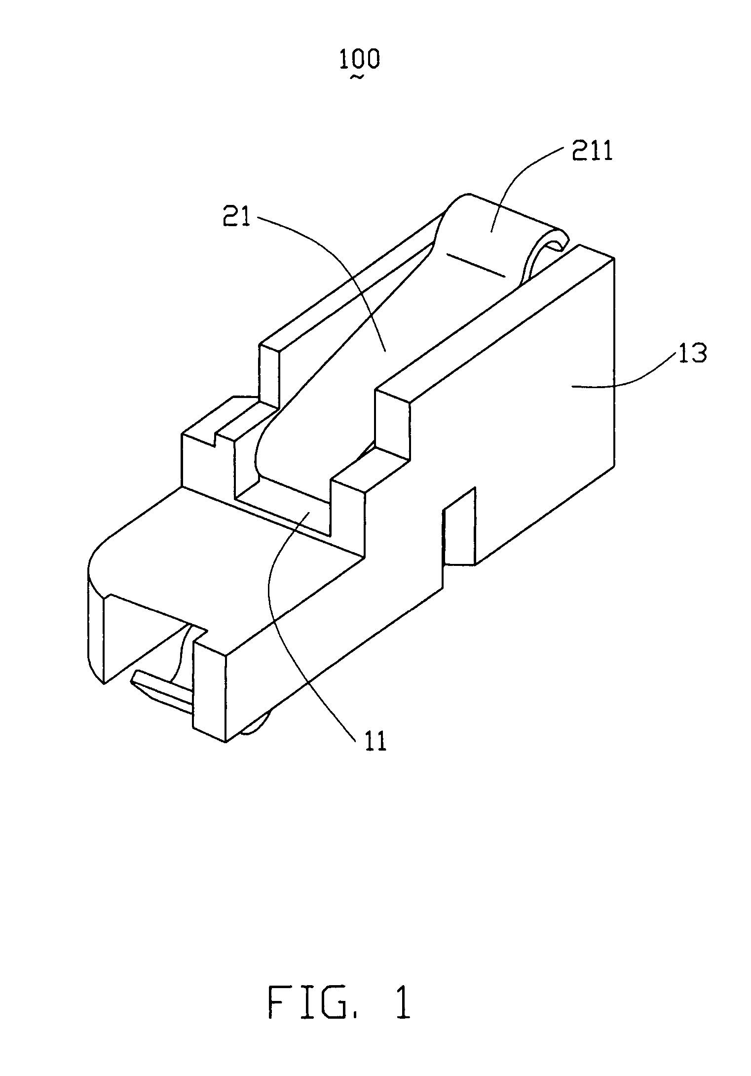
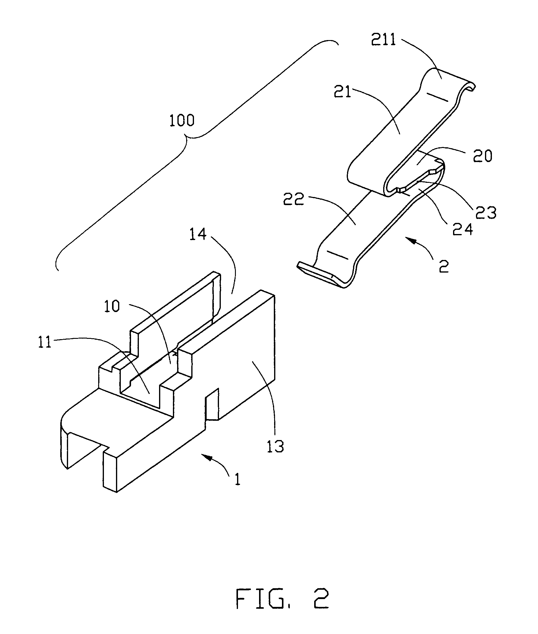
[0019]Referring to the drawings in greater detail, and first to FIGS. 1 and 2, an electrical connector 100 according to the present invention includes an insulative housing 1 and a conductive press fit contact 2 assembled to the housing 1.

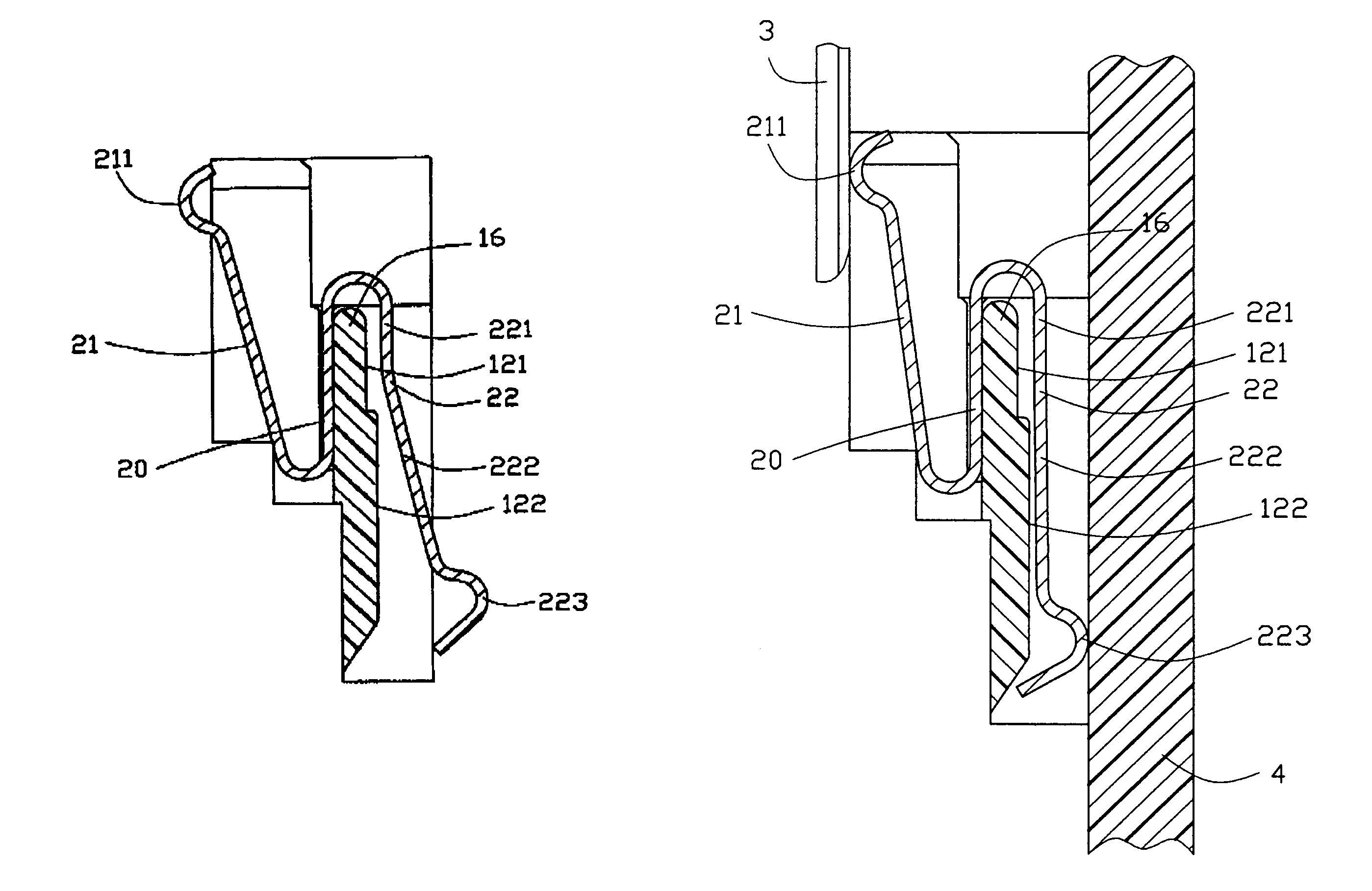
[0020]Referring to FIGS. 1–4, the housing 1 includes a substantially flat board 10 and opposite side walls 13 upwardly and downwardly projecting beyond the board 10. The board 10 includes a top surface 11 and a bottom surface 12. The t...


PUM


Abstract

An electrical connector (100) includes an insulative housing and a conductive contact assembled to the housing. The housing including a board (10) and opposite side walls (13) projecting upwardly and downwardly beyond the board. The board includes a top surface (11) and a bottom surface (12). The contact includes a base portion (20), a first spring arm (21) for engaging with an antenna (3) and a second spring arm (22) for resiliently pressing a printed circuit board (4). The second spring arm includes a retention portion (221) and a resilient portion (222) extending from the distal end of the retention portion. A bent is formed at a location between the retention portion and the resilient portion, whereby providing the resilient portion with enough flexibility.

Description

BACKGROUND OF THE INVENTION[0001]1. Field of the Invention[0002]The present invention relates to an electrical connector and more particularly, to an improved electrical connector for interconnection an antenna with a printed circuit board.[0003]2. Description of the Related Art[0004]It is becoming increasingly common practice to connect a plurality of terminals extending from an electrical connector with a plurality of circuit traces on a printed circuit board by mounting the connector on the same surface of the printed circuit board. Each terminal is coated with a solder composition. After a placement of the connector on the surface of the printed circuit board, the solder composition is melted so as to obtain the bond between the terminals and the circuit traces, thereby to obtain the electrically connection between the connector and the printed circuit board. One conventional electrical connector is disclosed in U.S. Pat. No. 6,227,877 issued to Mou on May 8, 2001. In this paten...

Claims


Application Information

Patent Timeline
Patent Type & Authority Patents(United States)
IPC IPC(8): H01R12/00H01R4/48H01R13/24H01R13/41H01R13/50
CPCH01R13/2435H01R13/2442H01R12/714H01R13/50H01R2201/02H01R13/41
Inventor DU, SHAOPINGZHENG, QISHENG
Owner HON HAI PRECISION IND CO LTD
Why Eureka
Try Eureka