Dynamic image processing method and device and medium

a technology of dynamic image and processing method, applied in the field of motion image processing method and device, can solve the problems of imposing a burden on the operator, difficult to apply a method using a glove in a particular, and inability to achieve object tracking properly

Inactive Publication Date: 2006-01-31
SANYO ELECTRIC CO LTD
View PDF17 Cites 267 Cited by
  • Summary
  • Abstract
  • Description
  • Claims
  • Application Information

AI Technical Summary

Benefits of technology

[0039]Preferably, the step of extracting shape characteristic, comprises the steps of extracting a contour based on edge information of an input image of the object detecting characteristic including a bending point, which is a point with a quick change of an edge gradient direction based on edge information, a curving point, which is a point on a contour with inversion of a curvature sign and a moderate change of an edge gradient direction, and a transition point, which is a point on a contour with a change of a curvature from zero to other value, or vice versa, and a moderate change of an

Problems solved by technology

The above mentioned motion image processing methods and devices have problems as described below.(1) A method using a marker attached on a finger tip requires marker identification and information on positional relationship among markers.(2) It is difficult to apply a method using a glove in a particular color to a background containing the same color as that of the glove or to an image expressed in monochrome tones.(3) A method using a data glove and so on imposes a burden on an operator.
This, however, has a problem such that rotation or size change of an object may result in a change of an image pattern appearing in an image frame, and matching and thus object tracking cannot be achieved properly.
Although these methods can handle ob

Method used


Image

  • Dynamic image processing method and device and medium
  • Dynamic image processing method and device and medium
  • Dynamic image processing method and device and medium

Examples


Embodiment Construction

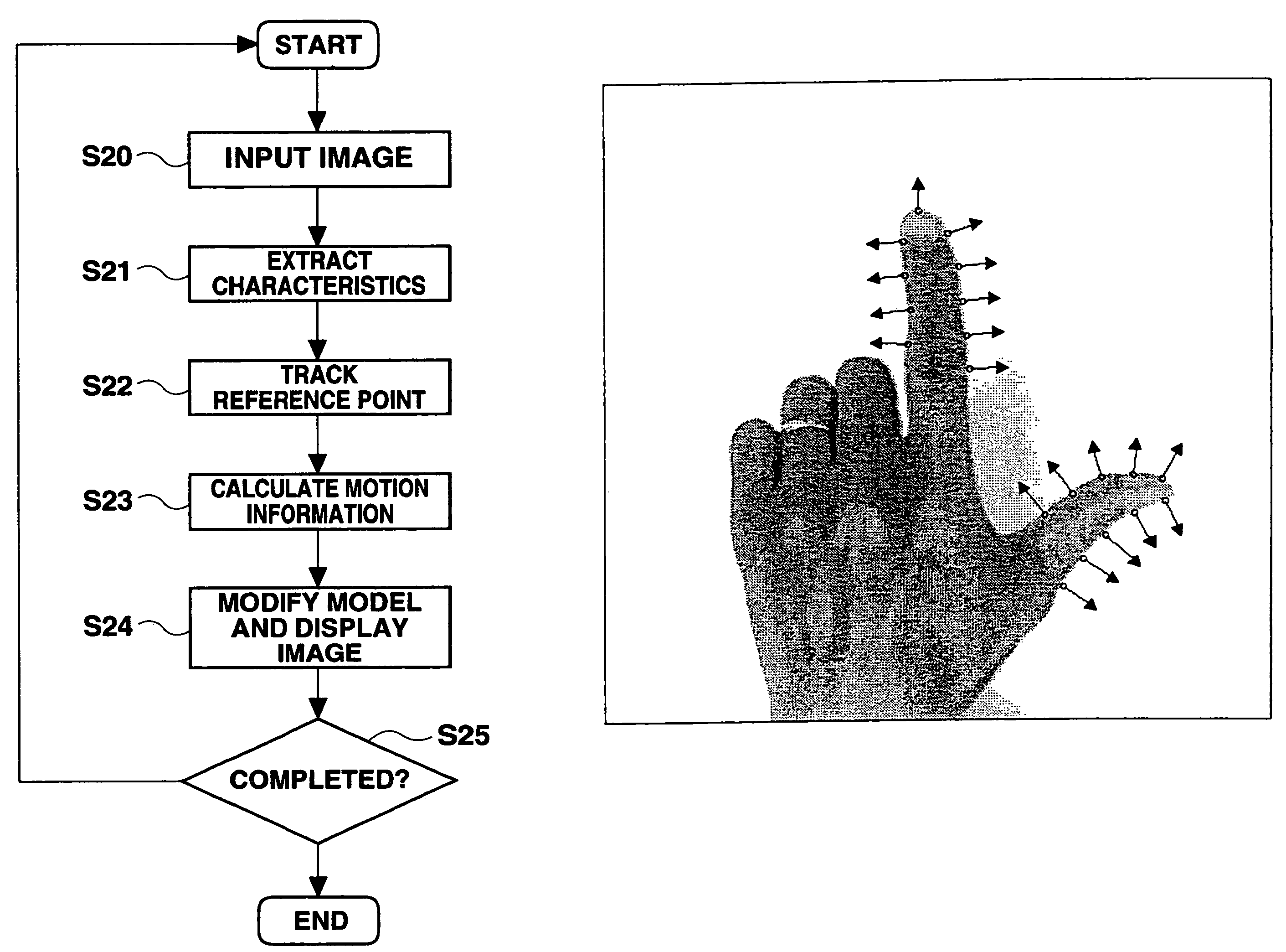
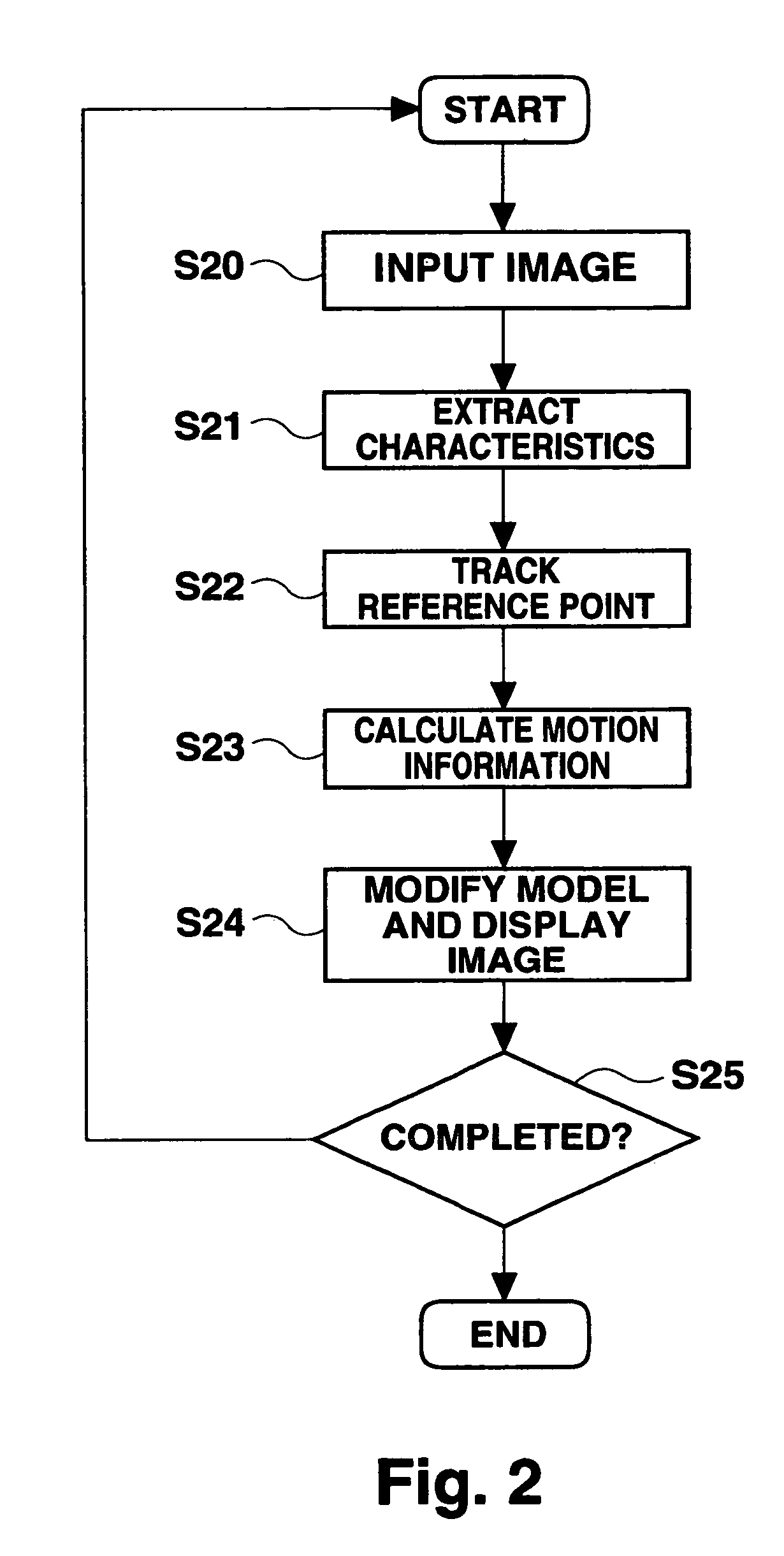
[0077]Preferred embodiments of the present invention will be described with reference to the accompanying drawings.

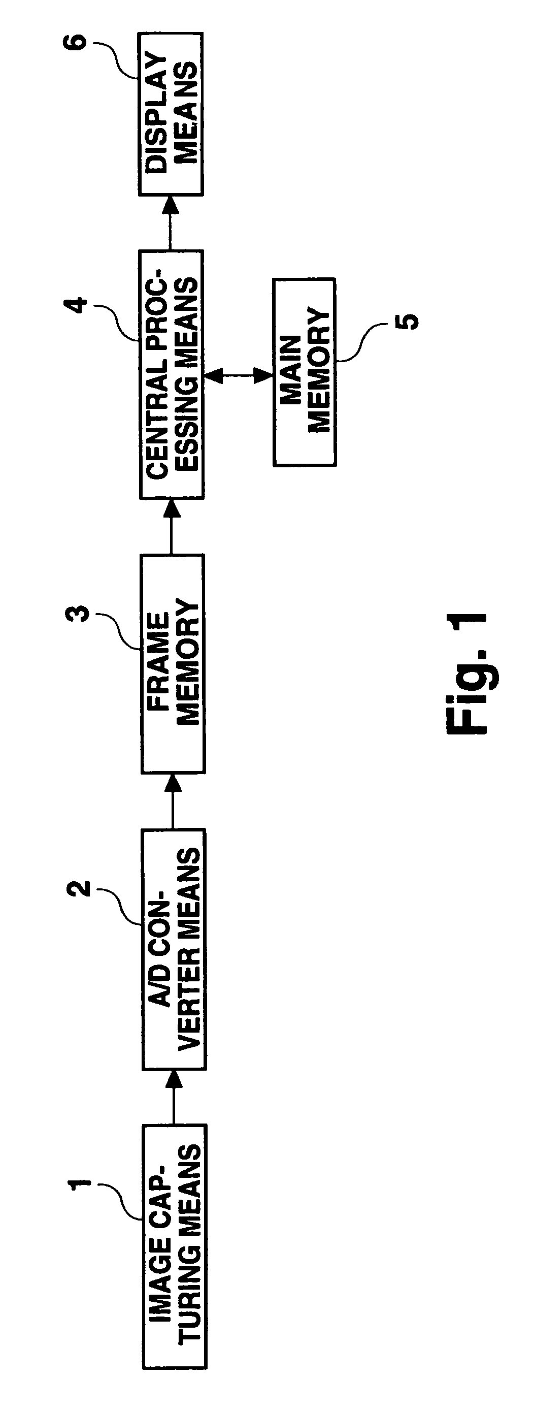
[0078]FIG. 1 is a schematic diagram showing a structure of a motion image processing device of the present invention. 1 is an image capturing means having an image sensor for capturing an image of an object, and specifically is a camera. 2 is A / D converter means for converting image information in the form of an analogue signal captured by the image capturing means 1 into image information in the form of a digital signal. 3 is a frame memory for storing digital image information, converted by the A / D converter means, for every time series frame. 4 is a central processing unit (CPU) for monitoring and controlling all of the processing devices, storing algorithm constituting of process flows of a motion image processing method of the present invention. 5 is a main memory for use in signal processing by the CPU 4. 6 is a display means for displaying an image processed by t...


PUM


Abstract

A motion image processing method and device for authenticating a user using a specific device, using motion information of an object. Time series monochrome images, obtained by photographing an object, using a camera, are input. An object is detected from an initial frame of the input time series images, using a basic shape characteristic, and a plurality of reference points to be tracked are automatically determined in the object. Then, corresponding points of the respective reference points are detected in an image frame other than the initial frame among the input time series images. Subsequently, motion information of a finger is calculated, based on the result of tracking the respective reference points and an assumption of limited motion in a 3D plane. Based on the calculated motion parameter, a solid object is subjected to coordinate conversion, and displayed if necessary. As a result of the tracking, a reference point in each frame is updated. Tracking, motion parameter calculation, and displaying are repeated with respect to subsequent frames.

Description

[0001]This application is the national phase of international application PCT / JP00 / 03179 filed 18 May 2000 which designated the U.S. and was not published under PCT Article 21(2) in English.TECHNICAL FIELD[0002]The present invention relates to a motion image processing method and device, and to a medium, and in particular to a characteristic extraction technique based on basic shape characteristics, to a motion image processing method and device in which motion information of an object is calculated while tracking the characteristic point in an image, and to a medium.BACKGROUND ART[0003]Conventional motion image processing methods and devices, in which characteristics are extracted from time series images obtained by photographing an object in motion and motion information of the object is estimated based on the extracted characteristics, include one method disclosed in Japanese Patent Laid-open Publication No. Hei 6-89342, in which a marker is attached to a finger tip, and another ...

Claims


Application Information

Patent Timeline
IPC IPC(8): G06K9/00B60R25/20B60R25/25B60R25/30G06T7/20G07C9/00
CPCB60R25/2045B60R25/252B60R25/305G07C9/00158G07C9/00563G06T7/2046E05Y2400/86E05F15/00G06T2207/10016G06T2207/30196G06T7/251G07C9/37
Inventor OUE, YASUHIROSUGIMOTO, KAZUHIDE
Owner SANYO ELECTRIC CO LTD
Why Eureka
Try Eureka