
System and method to facilitate pattern recognition by deformable matching

a technology of pattern recognition and matching, applied in the field of pattern recognition, can solve the problems of limited use of the euclidean distance algorithm, arbitrarily large values of euclidean distance, and the inability of tangent distance to specify loose constraints,

Inactive Publication Date: 2006-01-31
MICROSOFT TECH LICENSING LLC
View PDF26 Cites 6 Cited by
  • Summary
  • Abstract
  • Description
  • Claims
  • Application Information

AI Technical Summary

Benefits of technology

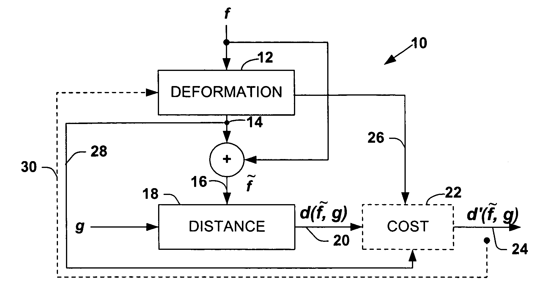
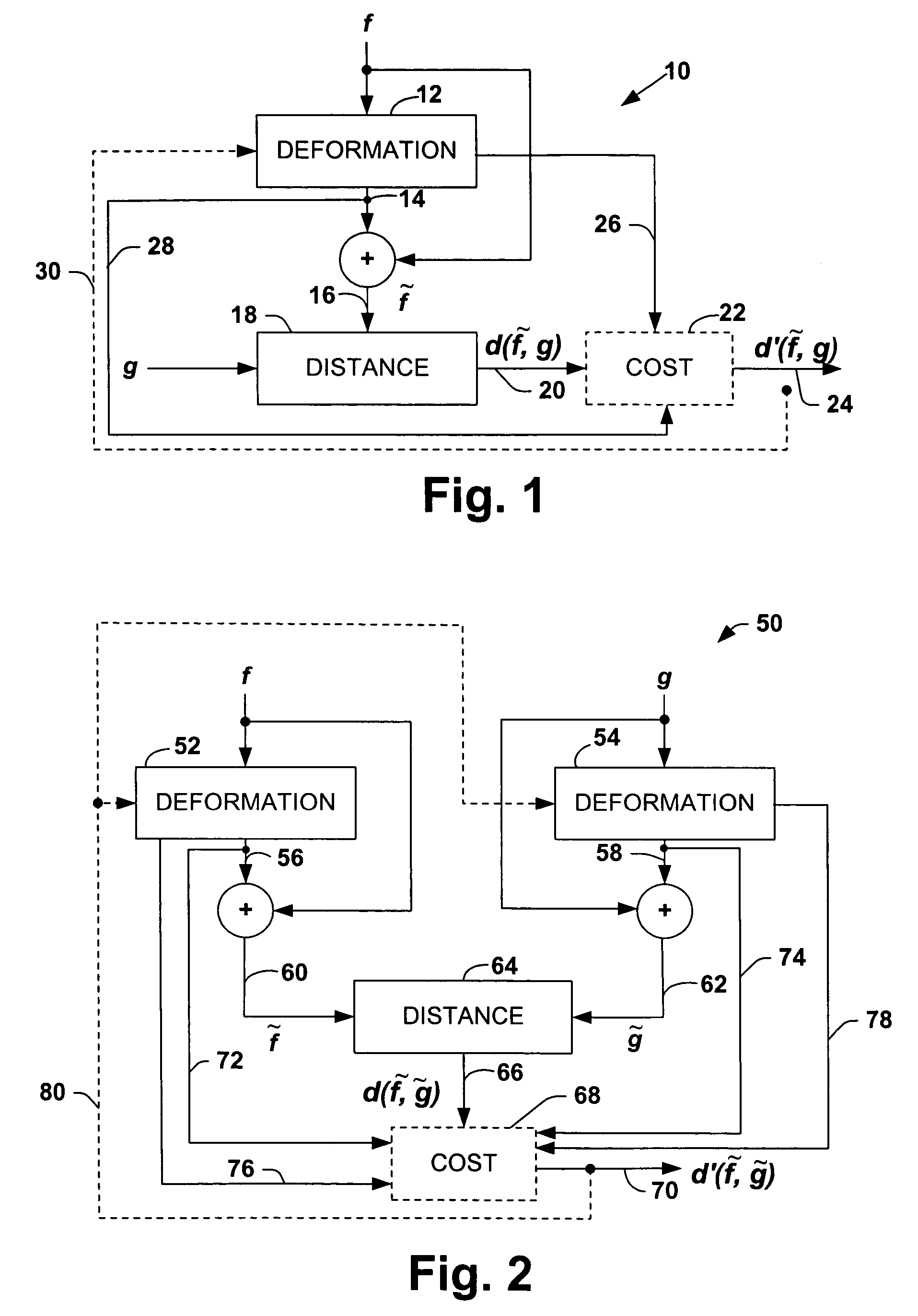
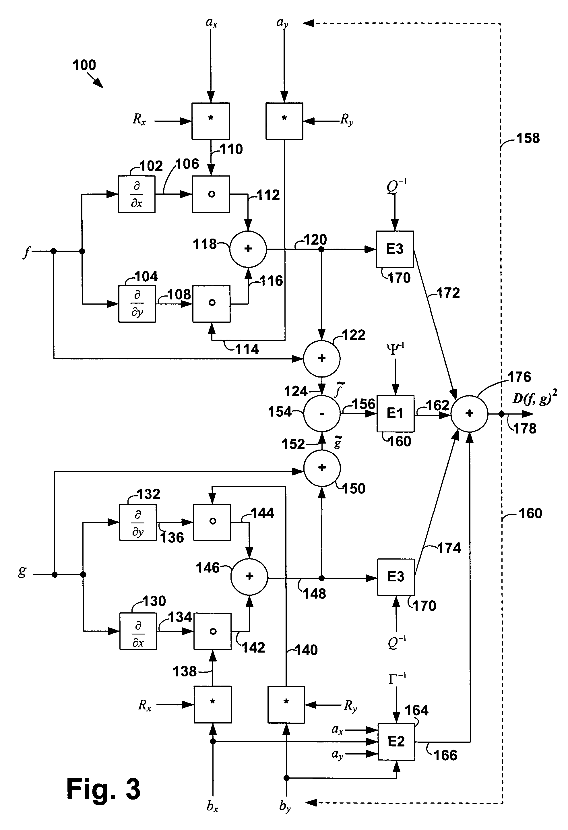
The present invention is a system and method for pattern recognition or matching between patterns. It involves applying a deformation field to a first pattern to create a deformation component, which is then added to the first pattern to create a deformed pattern. The deformation field is parameterized by smooth functional basis vectors and deformation coefficients associated with the first pattern. The minimum distance between the deformed pattern and a second pattern is determined by solving a linear system of equations. The invention allows for efficient pattern recognition and matching between patterns.

Problems solved by technology

The usefulness of the Euclidean distance algorithm is limited, however, because if f and g are not perfectly aligned, the Euclidean distance can yield arbitrarily large values.
A limitation of tangent distance approach, however, is that the transformations to which it is invariant generally must be known a-priori and precisely (e.g., translation, rotation, scaling, etc.).
Moreover, tangent distance has no mechanism to specify loose constraints such as small elastic displacements.
Any desired number of possible invariances can be included in any particular recognition process, provided that such invariances are known a priori, which is not always possible.
Although this method produces excellent results on practical problems, the amount of computation grows linearly with the total number of possible transformations in the input.
With the factor analysis approach, however, a large amount of data is needed to accurately model the deformations.
Learning also is susceptible to local optima that might confuse deformed data from one cluster with data from another cluster.

Method used


Image

  • System and method to facilitate pattern recognition by deformable matching
  • System and method to facilitate pattern recognition by deformable matching
  • System and method to facilitate pattern recognition by deformable matching

Examples


Embodiment Construction

[0033]The present invention provides a new model that may be utilized to measure similarity between patterns to facilitate pattern recognition or matching. The present invention employs a deformation field that is a linear combination of functional basis vectors one or more patterns. The functional basis vectors may be represented as low frequency basis vectors, such as low-frequency wavelet basis vectors, which allow significantly fewer parameters to represent a wide range of realistic smooth deformations. In this way, a pattern recognition system, in accordance with the present invention, is less likely to use a deformation field to “erase” part of an image or “draw” a new part, because the field is usually not smooth.

[0034]In the following description, for purposes of explanation, certain details are set forth in order to provide a thorough understanding of the present invention. It will be evident to one skilled in the art, however, that the present invention may be practiced wi...


PUM


Abstract

A system and method to facilitate pattern recognition or matching between patterns are disclosed that is substantially invariant to small transformations. A substantially smooth deformation field is applied to a derivative of a first pattern and a resulting deformation component is added to the first pattern to derive a first deformed pattern. An indication of similarity between the first pattern and a second pattern may be determined by minimizing the distance between the first deformed pattern and the second pattern with respect to deformation coefficients associated with each deformed pattern. The foregoing minimization provides a system (e.g., linear) that may be solved with standard methods.

Description

CROSS REFERENCE TO RELATED APPLICATION[0001]This application is a continuation of U.S. application Ser. No. 09 / 748,564 entitled SYSTEM AND METHOD TO FACILITATE PATTERN RECOGNITION BY DEFORMABLE MATCHING having a filing date of Dec. 22, 2000, now U.S. Pat. No. 6,785,419. The aforementioned application is incorporated herein by reference.TECHNICAL FIELD[0002]The present invention relates to pattern recognition and, more particularly, to a system and method to facilitate pattern recognition by deformable matching.BACKGROUND OF THE INVENTION[0003]Pattern recognition systems are employed in various areas of technology to help classify and / or match a test pattern relative to one or more known prototype patterns. Examples of pattern recognition applications include image analysis and classification, handwriting recognition, speech recognition, man and machine diagnostics, industrial inspection, medical imaging, etc.[0004]In a pattern recognition system, it is common to store large amounts ...

Claims


Application Information

Patent Timeline
Patent Type & Authority Patents(United States)
IPC IPC(8): G06K9/48G06K9/64
CPCG06K9/6206Y10S707/99936G06V10/754
Inventor JOJIC, NEBOJSASIMARD, PATRICE
Owner MICROSOFT TECH LICENSING LLC
Learn More