
Dispersion compensated optical fiber transmission system and module including micro-structured optical fiber

a technology of optical fiber and transmission system, applied in the direction of optical fiber with desired dispersion, cladded optical fibre, instruments, etc., can solve the problems of excessive amount of fiber needed to achieve such compensation, complicated installation of the system, and system may suffer from excessive insertion loss

Inactive Publication Date: 2006-01-31
CORNING INC
View PDF48 Cites 27 Cited by
  • Summary
  • Abstract
  • Description
  • Claims
  • Application Information

AI Technical Summary

Problems solved by technology

This compensation scheme avoids the drawbacks associated with the dispersion compensation module, namely that the length of dispersion compensating fiber does not contribute to the span length, but necessarily complicates the installation of the system.
However, to accomplish dispersion compensation across the entire wavelength band of interest, the amount of fiber needed to accomplish such compensation may be excessive.
Moreover, such systems may suffer from excessive insertion loss.

Method used


Image

  • Dispersion compensated optical fiber transmission system and module including micro-structured optical fiber
  • Dispersion compensated optical fiber transmission system and module including micro-structured optical fiber
  • Dispersion compensated optical fiber transmission system and module including micro-structured optical fiber

Examples


Embodiment Construction

[0038]Reference will now be made in detail to the present preferred embodiments of the invention, examples of which are illustrated in the accompanying drawings. Wherever possible, the same reference numbers will be used throughout the drawings to refer to the same or like parts.

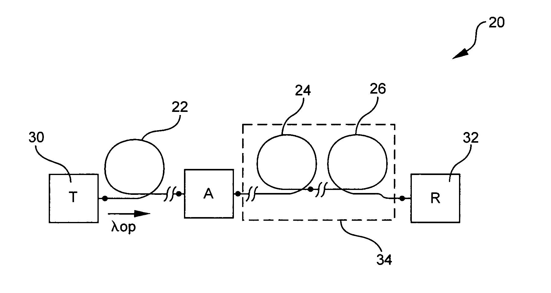
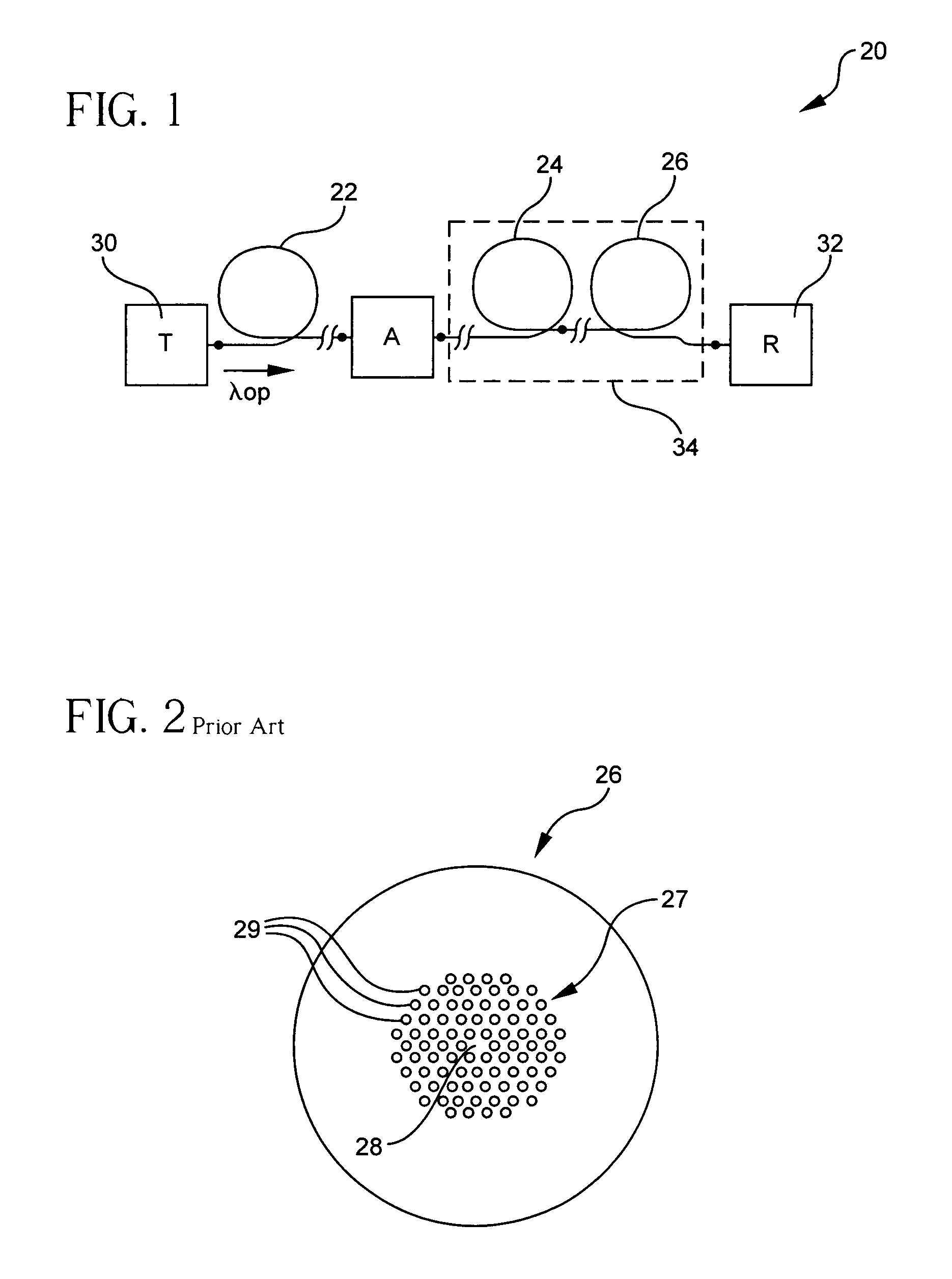
[0039]An exemplary embodiment of the optical transmission system 20 in accordance with the invention is shown in FIG. 1. The optical transmission system 20 includes and optical fiber span having a length of transmission fiber 22 optically coupled in series relationship to a length of dispersion compensating fiber 24 which is likewise optically coupled in series relationship to a micro-structured fiber 26. The optical coupling may be through direct splicing, through optical components or devices, through connectors or through bridge or other transition fibers. Bridge fiber may be employed between the dispersion compensating fiber 24 and the micro-structured fiber 26 when the effective areas or mode fields of ...


PUM


Abstract

Disclosed is an optical transmission system and module which includes a negative dispersion, dispersion compensating optical fiber coupled to a micro-structured optical fiber (such as band gap fiber, photonic crystal fiber or holey fiber) for compensating for the accumulated dispersion in a transmission fiber. The optical transmission system and module in accordance with the invention provides substantially equal compensation of total dispersion over an operating wavelength band, reduced overall system length, and lower insertion loss.

Description

BACKGROUND OF THE INVENTION[0001]1. Field of the Invention[0002]The present invention relates generally to optical fiber transmission systems, and particularly to a transmission systems designed such that they include compensation for dispersion across their length.[0003]2. Technical Background[0004]Dispersion compensation techniques in telecommunications systems or lines have been used successfully. A technique useful in lines already installed is one in which total dispersion (also called chromatic dispersion) is compensated for by an appropriately designed dispersion compensating fiber. For example, some systems include dispersion compensating fibers formed into a dispersion compensating module that can be inserted into the line at an access point, such as an end of the line. Such fibers typically have negative dispersion and may also have negative dispersion slope at 1550 nm. Several examples of dispersion compensating fibers may be found in U.S. Pat. Nos. 6,546,178; 6,445,864; ...

Claims


Application Information

Patent Timeline
Patent Type & Authority Patents(United States)
IPC IPC(8): G02B6/02H04B10/12G02B6/00G02B6/032G02B6/036G02B6/34H04B10/00H04B10/18
CPCG02B6/02261G02B6/02271G02B6/02333G02B6/02338H04B10/2525G02B6/02361G02B6/02366G02B6/03644G02B6/03677G02B6/29377G02B6/02347G02B6/0228
Inventor BURKE, JR., JAMES P.MUELLER, DIRK
Owner CORNING INC
Learn More