Adjustable hinges for orthopedic splints

a technology of orthopedic splints and hinges, which is applied in the field of hinged orthopedic splints and braces, to achieve the effects of convenient application of splints, convenient adjustment, and convenient engagement and displacement of detents

Inactive Publication Date: 2006-02-07
LENJOY ENG
View PDF8 Cites 95 Cited by
  • Summary
  • Abstract
  • Description
  • Claims
  • Application Information

AI Technical Summary

Benefits of technology

[0011]In a presently preferred embodiment of the invention, the detent is displaceable in a guide way defined between the upper plate and the cover assembly, and a biasing spring is contained in the guide way. The spring may be a coil spring compressed between the cover assembly and the detent. The cover assembly may include a spacer which is mounted between the upper plate and cover plate and defining the guide way for the detent, and a cover plate applied over the spacer for containing the detent in the guide way. The access aperture may be a slot in the cover plate, the slot being aligned with a direction of displacement of the detent. The detent preferably has a tool end receptacle such as a hole or depression adapted to receive the pointed tool and thereby to facilitate positive engagement and displacement of the detent by means of the tool end. The access aperture is preferably sized and shaped so as to allow visual confirmation of detent engagement with the toothed element.
[0012]Typically, the detent is engageable with an arcuate toothed edge supported on the lower plate, and the pivotal movement of the two plates of the splint comprises an arc including a zero angle position situated at an intermediate location along the arc, such that the plates may be moved through substantial angular ranges on either side of the zero angle position. The zero angle position may be centered along the arc such that the plates may be pivoted through equal angular ranges on either side of the zero angle position. The zero angle position may be situated along the arc such that the two plates are aligned in a straight line when the hinge is set to the zero angle position. By providing for a range of angular movement of the hinge to one side or the other of the zero position, the splint may be applied to a right side or a left side of a limb, eliminating the need for special left handed or right handed splints. In another aspect of the invention the hinge has a locking element removably engageable for holding the detent out of its engaged condition to thereby facilitate application of the splint to a patient's limb with the hinge free to rotate through its full 240 degree arc of movement, so that the therapist can bend the splint quickly and easily to match the position of the patient's limb. That is, the splint angle can be easily adjusted to the angle of the patient's joint rather than having to reposition the patient's limb to fit the angle of the splint. Once the splint is applied and fastened to the limb, the detent locking element facilitates setting of the hinge angular range by holding the detent out of engagement while the range setting elements or wheels are properly positioned, after which the detent may be released into engagement with the range setting elements.

Problems solved by technology

A continuing problem encountered in this class of splints is to provide for convenient adjustment of the splint's angular settings by a therapist while also making the splint's settings relatively resistant to tampering by the patient who may become impatient with the course of therapy and wish to reset the splint to suit his or her immediate comfort.

Method used


Image

  • Adjustable hinges for orthopedic splints
  • Adjustable hinges for orthopedic splints
  • Adjustable hinges for orthopedic splints

Examples


Embodiment Construction

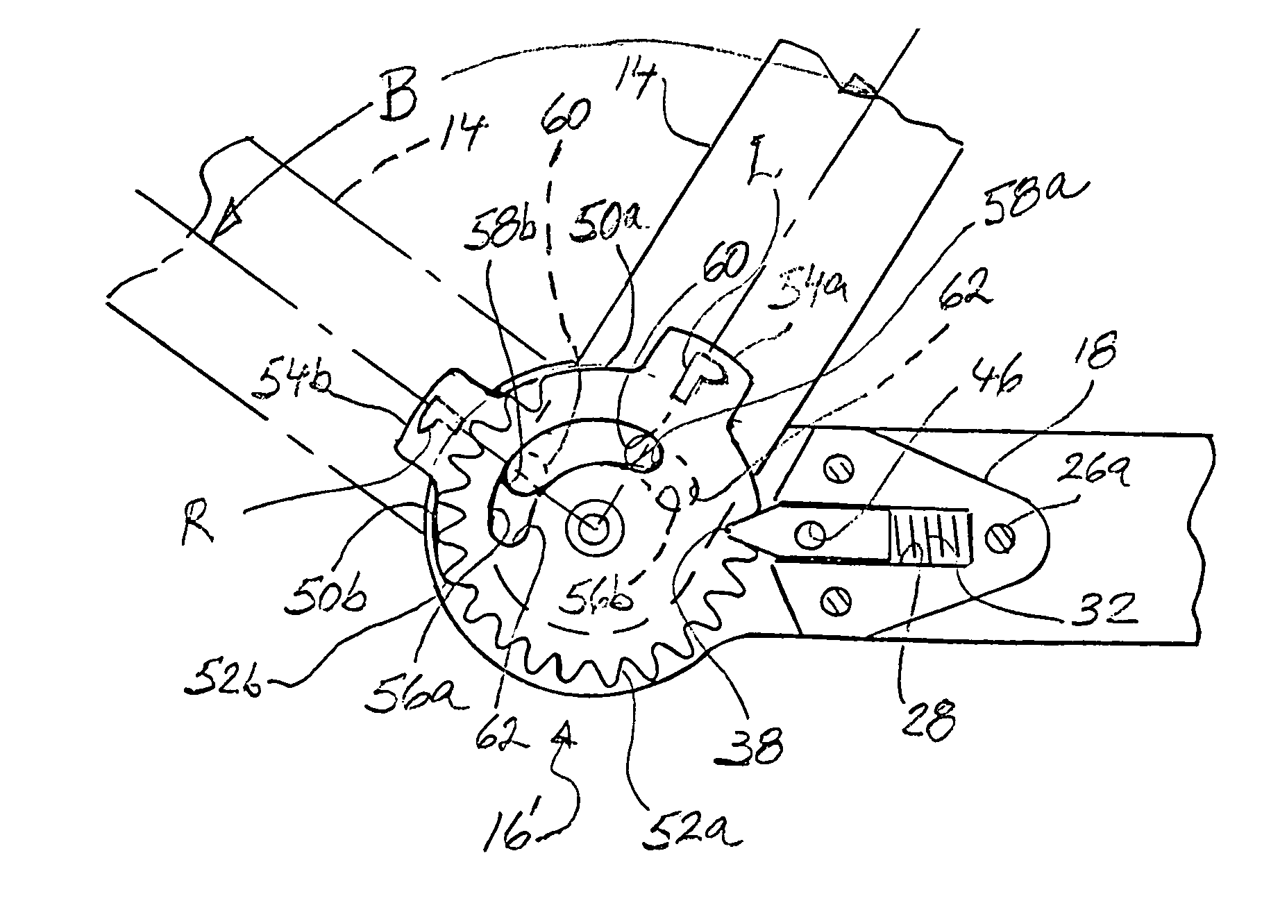
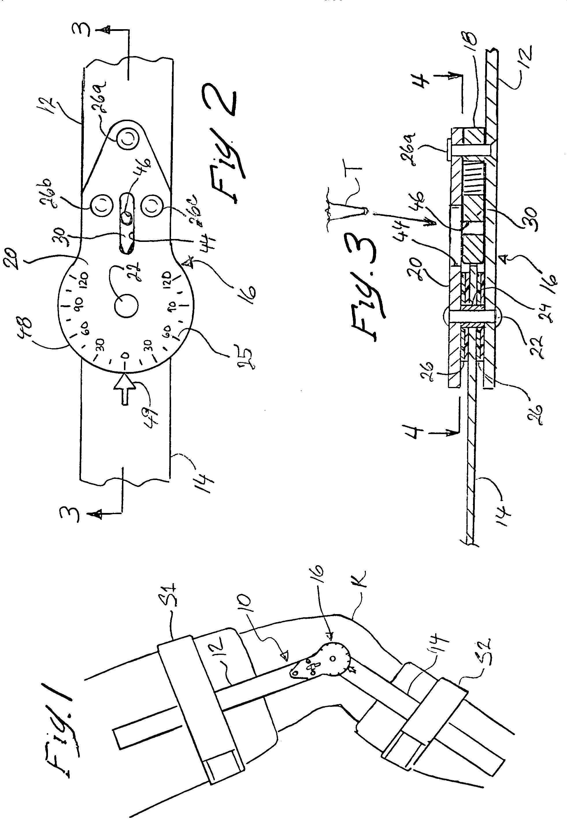
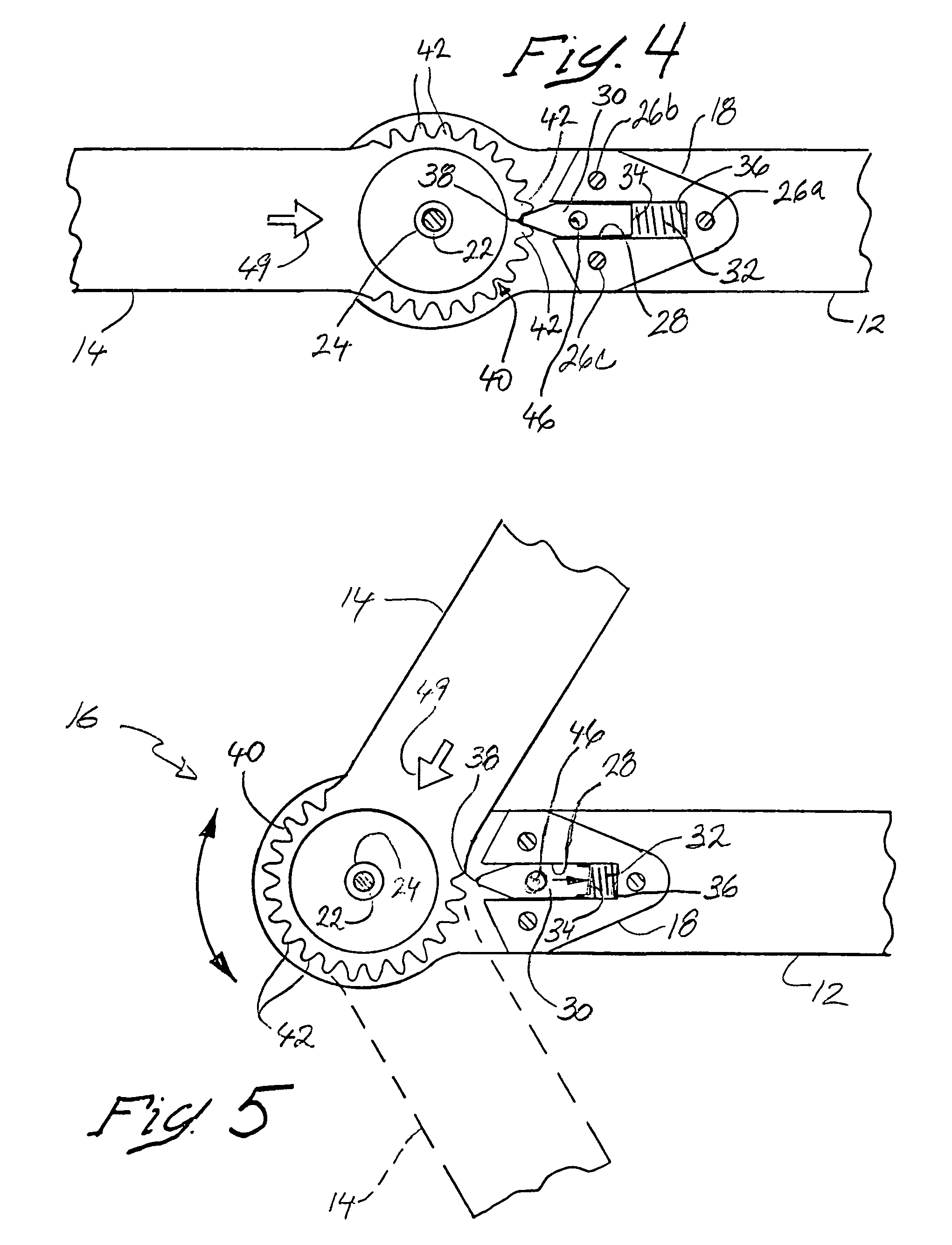
[0025]With reference to the drawings wherein like elements are designated by like numerals, FIG. 1 depicts an orthopedic splint or knee brace 10 applied to the knee joint K of a patient. The brace includes an upper plate 12 and a lower plate 14 connected to each other for pivotal movement by a hinge 16. The upper plate is attached to the thigh of the patient's leg by an upper strap S1 and the lower plate is similarly attached to the leg below the knee by a lower strap S2 so that the hinge 16 lies adjacent to and pivots with bending of the knee. Typically, two similar knee braces 10 are applied to the knee joint of the patient, one brace on the outside of the leg, as shown in FIG. 1, and an opposite second brace (hidden in FIG. 1) on the inside of the leg. The two braces are generally parallel to each other and provide lateral support to the knee joint while allowing flexing of the knee joint in a plane parallel to the planes of movement of the brace hinge 16. In the course of rehabi...


PUM


Abstract

A hinge for an orthopedic splint has two plates hinged for pivotal movement relative to each other and a detent engageable for locking the plates at a selected angle to each other, and a spring urging the detent into engagement. The detent is protected in a recessed guideway against operation with the unaided hand to discourage tampering with the splint settings by the patient fitted with same, but is retractable with a pointed tool inserted in the recess or a removable screw threaded in the detent as a finger hold. The screw may also pass through the detent and if tightened against an underlying plate keeps the detent disengaged to facilitate adjustment of the splint. The hinge allows left and right hand angular settings of the splint to either side of a zero angle for ambidextrous use of the splint, and radial tabs with directional markings are provided as visual indicators of the angular setting of the splint hinge.

Description

BACKGROUND OF THE INVENTION[0001]1. Field of the Invention[0002]This invention pertains to the field of hinged orthopedic splints and braces of the type applied across the joint of a limb such as a knee or elbow for limiting movement of the joint for therapeutic purposes, and is more particularly directed to certain improvements in the hinge for such splints.[0003]2. Background of the Invention[0004]Knee and elbow splints or braces typically have an upper plate and a lower plate connected to each other by a hinge such that, when the upper plate is attached to the limb above the joint and the lower plate to the limb below the joint, the patient may flex the limb at the joint. Many such splints are known and are commonly used in the course of orthopedic rehabilitation. It is also known to provide splints with adjustable hinges which enable a therapist to set limits to the arc of movement of the splint and hence of the patient's joint, as may be required by the patient's condition and ...

Claims


Application Information

Patent Timeline
Patent Type & Authority Patents(United States)
IPC IPC(8): E05D11/10
CPCA61F5/0125A61F2005/0158Y10T16/5402E05D11/1007Y10T16/54028E05D11/06
Inventor BENNETT, JOHN E.BRADLEY, WILLIS C.
Owner LENJOY ENG
Why Eureka
Try Eureka