Method and apparatus for detecting combustion instability in continuous combustion systems

a continuous combustion system and detection method technology, applied in lighting and heating apparatus, instruments, machines/engines, etc., can solve problems such as combustion instability, destructive pressure oscillations or acoustic oscillations, and premixing also reduces the possibility of localized fuel rich areas

Inactive Publication Date: 2006-02-07
WOODWARD GOVERNOR CO
View PDF19 Cites 48 Cited by
  • Summary
  • Abstract
  • Description
  • Claims
  • Application Information

AI Technical Summary

Benefits of technology

[0007]The invention provides an apparatus and method to sense the presence of combustion instability, even at very low levels, so that an operator or a closed loop control system can take mitigating action to either restore combustion stability or shut down the combustion process (in the turbine or afterburner).

Problems solved by technology

The premixing also decreases the possibility of localized fuel rich areas where carbon monoxides and unburnt hydrocarbons are not fully oxidized.
One of the more difficult challenges facing manufacturers of lean premix gas turbines and other continuous combustion systems is the phenomenon of combustion instability.
Combustion instability is the result of unsteady heat release of the burning fuel and can produce destructive pressure oscillations or acoustic oscillations.
In lean premix gas turbines, combustion instability can occur when the air-fuel ratio is near the lean flammability limit, which is where turbine emissions are minimized.
However, if the air / fuel ratio is too lean, the flame will become unstable and create pressure fluctuations.
Depending on the magnitude and frequency, this oscillation can create an audible noise which is sometimes objectionable, but a much more serious effect can be catastrophic failure of turbine components due to high cycle fatigue.
The most severe oscillations are those that excite the natural frequencies of the mechanical components in the combustion region, which greatly increases the magnitude of the mechanical stress.
However, as components wear out or fuel composition changes, the combustion process can still become unstable.

Method used


Image

  • Method and apparatus for detecting combustion instability in continuous combustion systems
  • Method and apparatus for detecting combustion instability in continuous combustion systems
  • Method and apparatus for detecting combustion instability in continuous combustion systems

Examples


Embodiment Construction

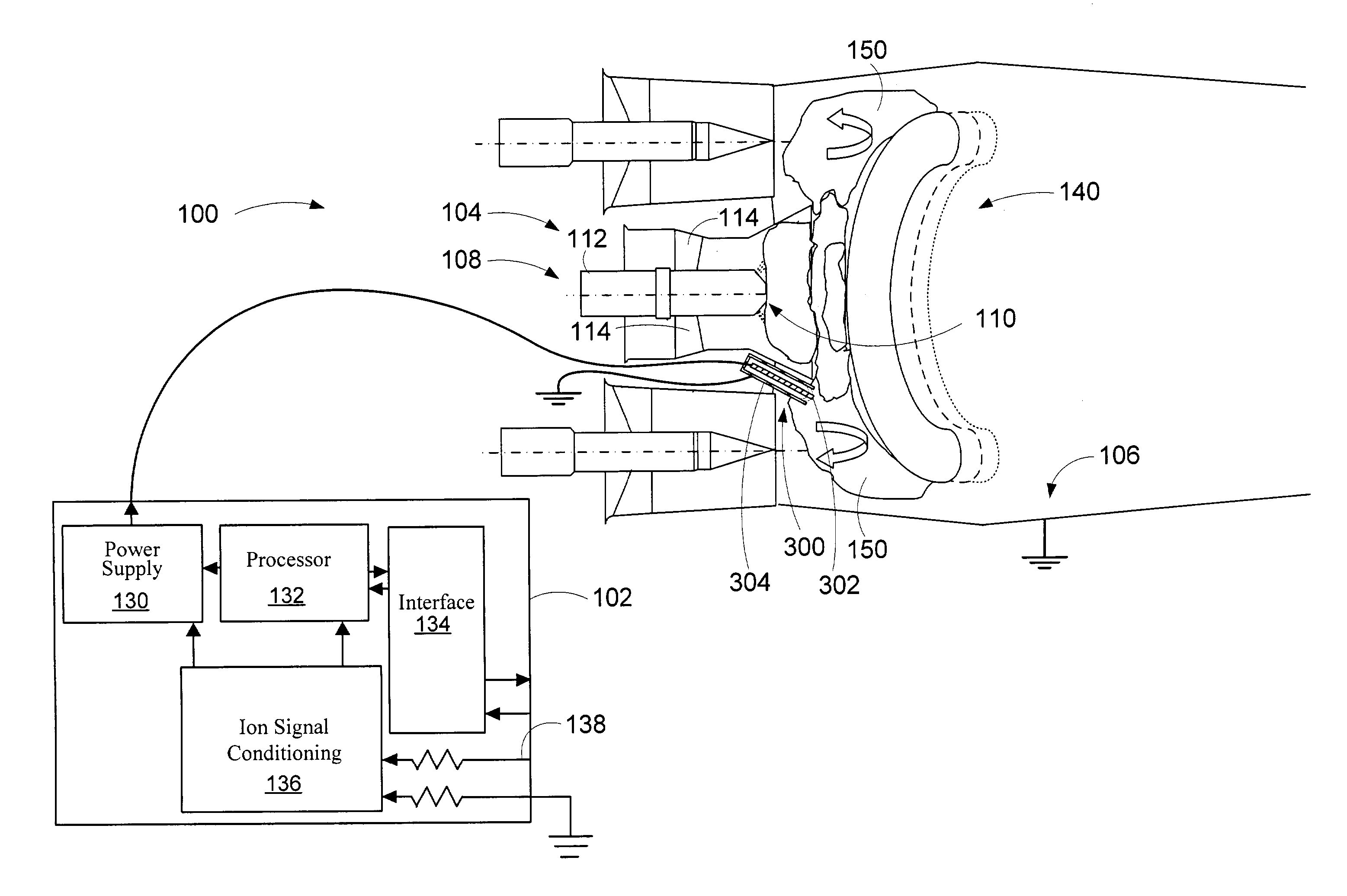
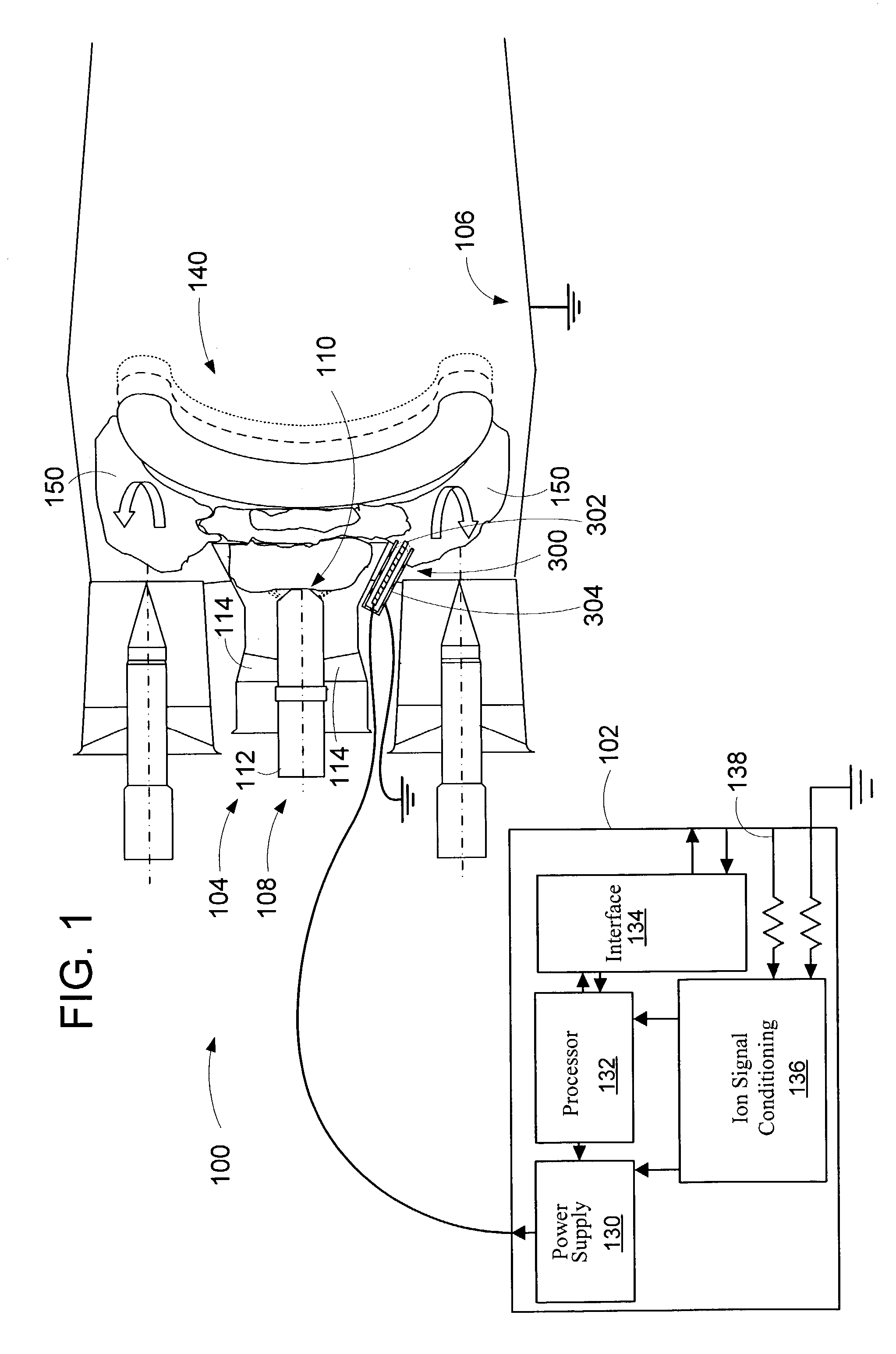
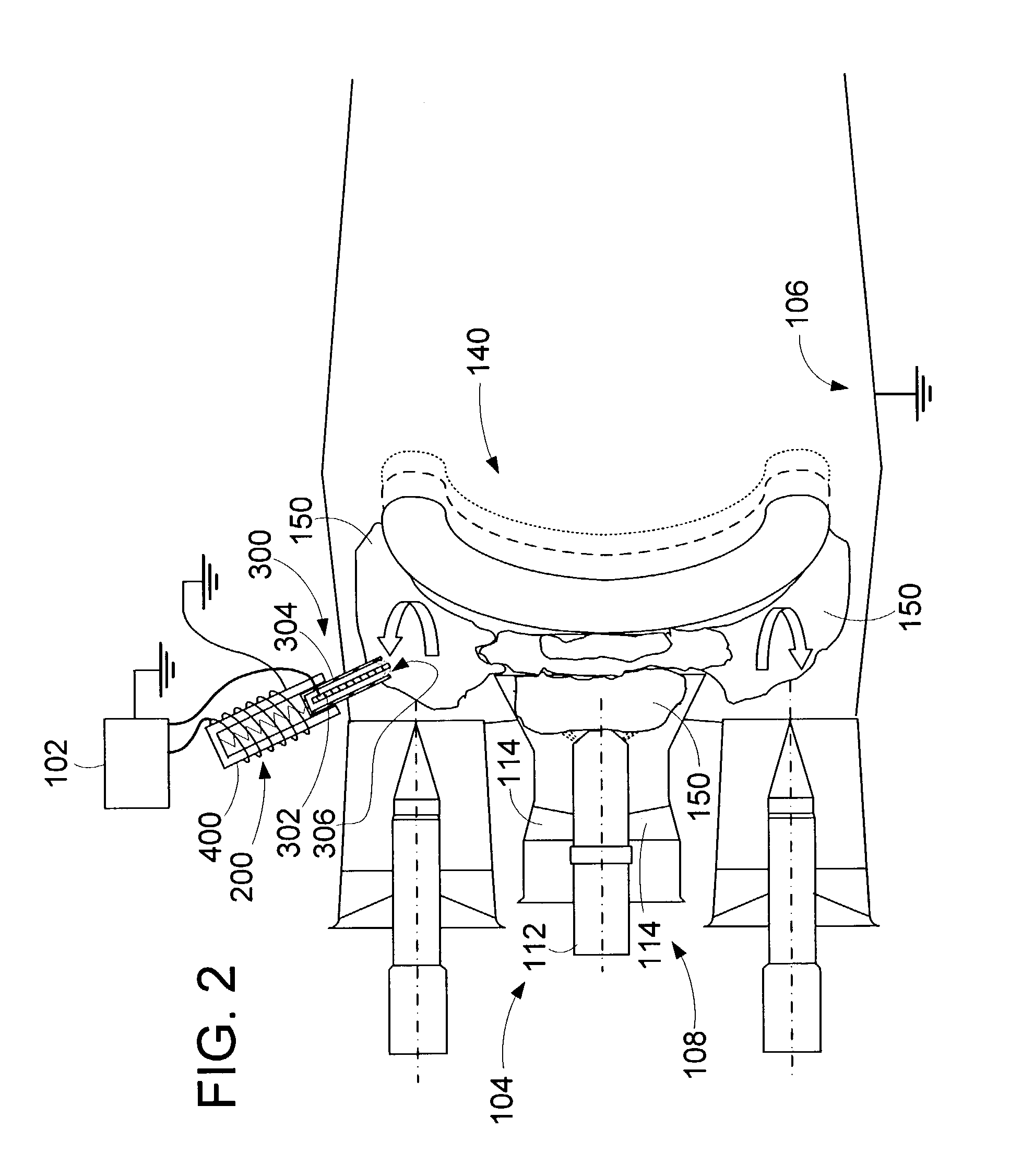
[0024]The present invention provides a method and apparatus to sense combustion instability and / or the onset of combustion instability in a combustion region of a continuous combustion system such as a gas turbine, industrial burner, industrial boiler, or afterburner utilizing ionization signals. The invention may be used with any hydrocarbon fuels, such as liquid or gaseous fuels, that produce free ions in the flame when the fuel is burned. The magnitude of the free ions in the flame is proportional to the concentration of hydrocarbons, and therefore the measured ion current is also proportional to the magnitude of free ions. Oscillations in the flame produce oscillations in the hydrocarbons, which in turn, results in oscillations in the ionization signal. When those ion current oscillations have been properly correlated to pressure oscillations, the ion signal gives a very clear indication of the pressure oscillations. The oscillation of the ion signal is typically correlated in a...


PUM

PropertyMeasurementUnit
frequencyaaaaaaaaaa
frequencyaaaaaaaaaa
frequencyaaaaaaaaaa

Abstract

An apparatus and method to sense the onset of combustion stability is presented. An electrode is positioned in a turbine combustion chamber such that the electrode is exposed to gases in the combustion chamber. The electrode may be integrated with an igniter. A control module applies a voltage potential to the electrode and detects a combustion ionization signal and determines if there is an oscillation in the combustion ionization signal indicative of the occurrence of combustion stability or the onset of combustion instability. The control module broadcasts a notice if the parameters indicate the combustion process is at the onset of combustion instability or broadcasts an alarm signal if the parameters indicate the combustion process is instable. Combustion parameters are adjusted to drive the combustion process towards stability.

Description

CROSS-REFERENCE TO RELATED PATENT APPLICATIONS[0001]This patent application is a continuation-in-part of copending U.S. patent application Ser. No. 10 / 329,664, filed Dec. 26, 2002.FIELD OF THE INVENTION[0002]The present invention relates generally to continuous combustion systems, and more particularly relates to such systems operating near the onset of combustion instability.BACKGROUND OF THE INVENTION[0003]Continuous combustion systems such as gas turbine engines are used in a variety of industries. These industries include transportation, electric power generation, and process industries. During operation, the continuous combustion system produces energy by combusting fuels such as propane, natural gas, diesel, kerosene, or jet fuel. One of the byproducts of the combustion process is emission of pollutants into the atmosphere. The levels of pollutant emissions are regulated by government agencies. Despite significant reductions in the quantity of environmentally harmful gases emi...

Claims


Application Information

Patent Timeline
Patent Type & Authority Patents(United States)
IPC IPC(8): G01M15/00G01M99/00F23N1/02F23N5/12F23N5/24G01L23/22
CPCF23N1/022F23N5/123F23N5/242G01L23/225F23R3/286F23R3/343F05B2260/80F23D2900/00015F23N2041/20F23R2900/00013F23N2029/12F23N2229/12F23N2241/20
Inventor BENSON, KELLY J.
Owner WOODWARD GOVERNOR CO
Why Eureka
Try Eureka