Self-inking hand stamp

Inactive Publication Date: 2006-02-07
COLOP STEMPELERZEUGUNG SKOPEK GMBH & CO KG
View PDF20 Cites 8 Cited by
  • Summary
  • Abstract
  • Description
  • Claims
  • Application Information

AI Technical Summary

Benefits of technology

[0010]To obtain an information surface area that is as large as possible, as well as a symmetrical design that facilitates the manufacture, it is particularly advantageous if the receiving recess extends with a generally U-shaped cross section to both broad sides of the actuating frame, and if the transparent cover has a substantially U-shaped, curved cross section.
[0011]For mounting the transparent cover by simply snapping or locking it on, the transparent cover advantageously cover has locking projections located on its inner surface along the edge, for locking the cover in locking recesses located on the edge of the receiving recess. Provision is usefully made for at least one locking projection on the at least one broad side, and for a locking projection on the opposite edge on the top side, but preferably on the other broad side if the receiving recess extends toward both broad sides. The cover is shaped in a suitable form or with initial elastic tension, so that it is attached to the receiving recess and snapped on with elastic deformation. For safely securing the transparent, curved cover on the actuating frame, it is useful in this connection if a strip-like, center locking projection is molded onto each of the edges of the transparent cover, with a corresponding, oblong locking window located on the respective edge of the receiving recess being associated with such a locking projection.
[0012]Furthermore, it is advantageous for simplified mounting of the information sheet if the locking projections on the inner surface of the transparent

Problems solved by technology

On the other hand, it has been proposed also to provide receiving recesses for accommodating labels on the two broad sides of the actuating frame instead of on the top side in order to accommodate information labels in such recesses—compare AT 380 836 B. However, these various proposals all have been found unsatisfactory in practice but they were accepted because only these designs were viewed as useful in self-inking hand stamps in which the stamp housing resiliently supports the cap-shaped actuating frame, in spite of the fact that it has been known from DE 1 136 720 C to place a label on the head of the handle of a hand stamp that extended from the top side to the narrow sides and possibly also up to the broad sides of the hea

Method used


Image

  • Self-inking hand stamp
  • Self-inking hand stamp
  • Self-inking hand stamp

Examples


Embodiment Construction

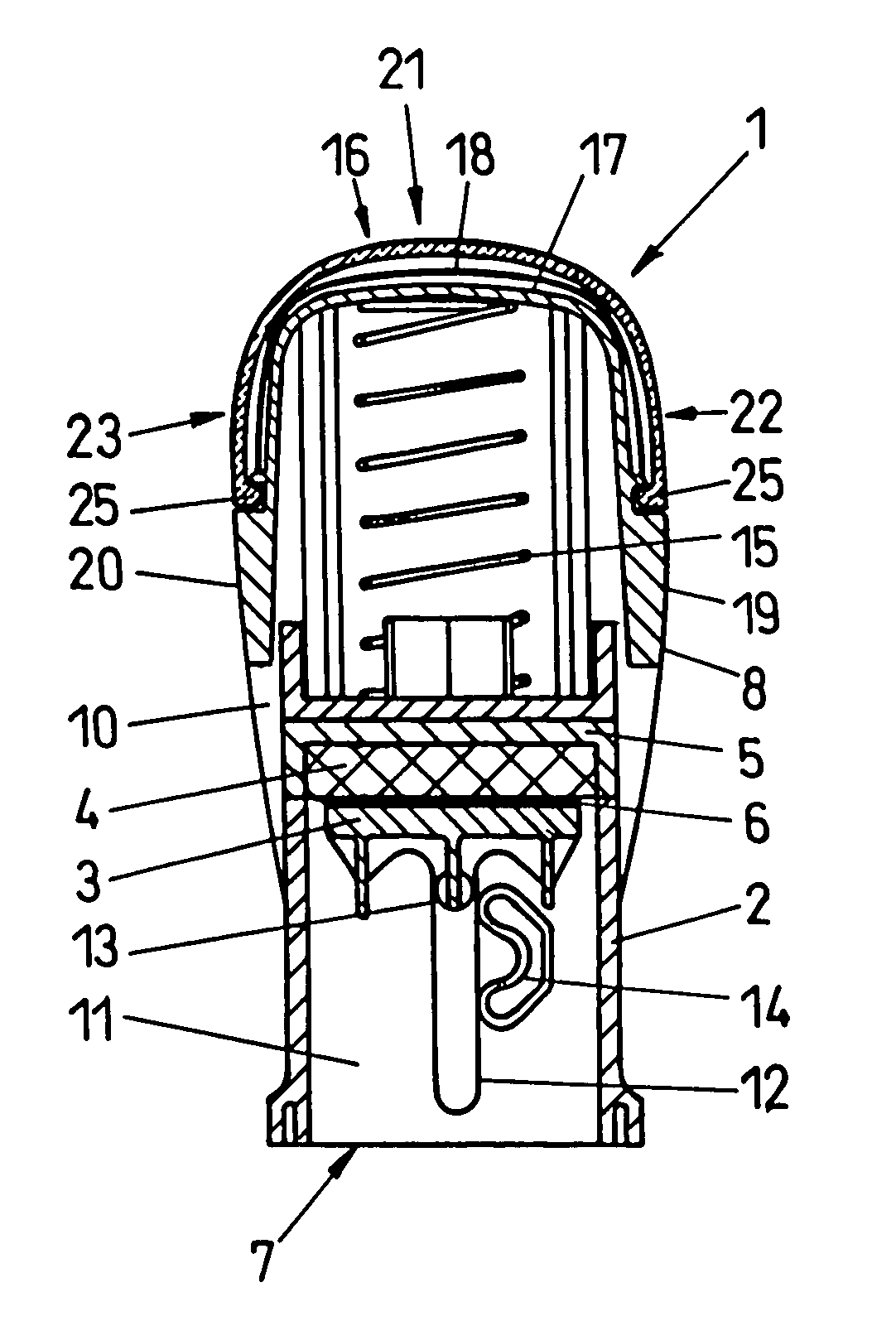
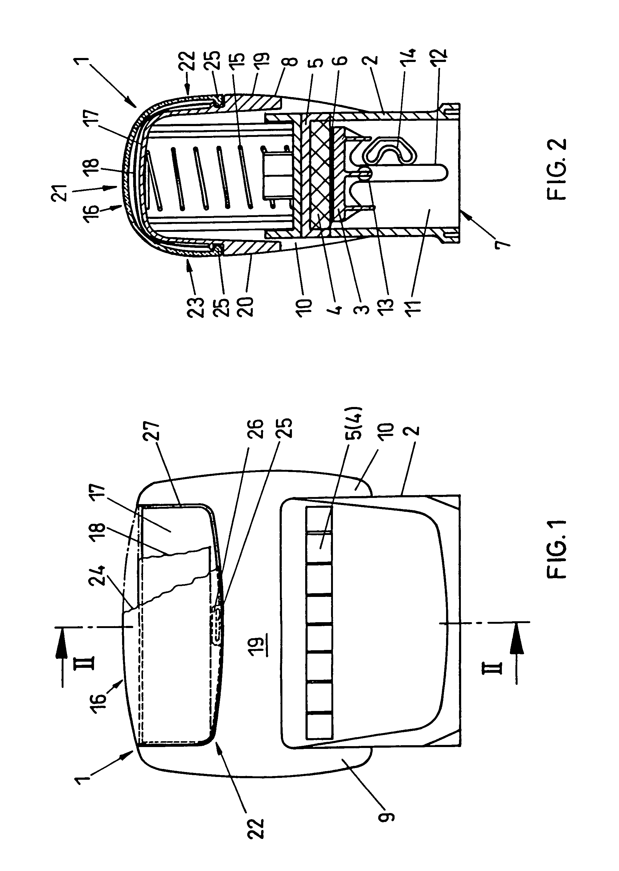
[0023]FIGS. 1 and 2 show a self-inking hand stamp 1 with upper impact inking, which comprises a stamp housing 2, in which a stamp aggregate 3 is movably arranged in a conventional manner. Said stamp aggregate 3 is shown in FIG. 2 in the upper normal or inking position, resting on an ink pad 4 in a pad drawer 5 pushed into a receptacle in the stamp housing 2. From said upper position, the stamp aggregate 3 can be moved down and swivelled at the same time by 180°, so that it is capable of producing an imprint on a document with its printing side 6 through the lower opening 7 of the stamp housing 2. For such actuation of the stamp, provision is made for an actuating frame 8 mounted on the stamp housing 2 in the manner of a cap. The actuating frame is comprised of the two legs 9, 10 (see FIG. 1) that slide along the two narrow side walls 11 (FIG. 2) of the stamp housing and are connected with the stamp aggregate 3 by pins 13 extending through a vertical guide slot 12. For reversing the ...


PUM


Abstract

A self-inking hand stamp (1) with upper impact inking, comprising a stamp housing (2) in which a stamp aggregate (3) is arranged that is capable of moving from an inking position on an ink pad (4) into a stamping position, with an actuating frame (8) as well as a reversing mechanism being associated with the stamp aggregate for said purpose, whereby the actuating frame (8) is mounted like a cap on the top part of the stamp housing (2), and comprises two legs (9, 10) for actuating the stamp aggregate (3), said legs resting against the stamp housing (2), and can be depressed relative to the stamp housing (2) against spring force, and is provided with a receiving recess (17) for accommodating an information sheet (18), with a transparent cover (24) being associated with the receiving recess (17). The receiving recess (17) extends from the top side (16) of the actuating frame (8) to the broad sides (19, 20) of the frame, and the transparent cover (24) is correspondingly curved from the top side to the broad side and embodied in the form of one single piece.

Description

CROSS REFERENCE TO RELATED APPLICATIONS[0001]Applicant claims priority under 35 U.S.C. §119 of Austrian Application No. GM 105 / 99, filed on 18 Feb. 1999. Applicant also claims priority under 35 U.S.C. §365 of PCT / AT00 / 00029, filed on 8 Feb. 2000. The international application under PCT article 21(2) was not published in English.BACKGROUND OF INVENTION[0002]1. Field of Invention[0003]The invention relates to a self-inking hand stamp with upper impact inking comprising a stamp housing in which a stamp aggregate is arranged that is capable of moving from an inking position on an ink pad to a stamping position, and an actuating frame with a reversing mechanism associated with the stamp aggregate for this purpose. The actuating frame comprised of a top side, two broad sides opposite each other, as well as two narrow sides opposite each other, is mounted on the upper part of the stamp housing in the form of a cap. The actuating frame comprises two legs resting laterally on the stamp housi...

Claims


Application Information

Patent Timeline
IPC IPC(8): B41K1/42B41K1/40B41K1/56
CPCB41K1/56B41K1/40
Inventor FABER, ERNST
Owner COLOP STEMPELERZEUGUNG SKOPEK GMBH & CO KG
Why Eureka
Try Eureka