EHB proportional solenoid valve with stepped gap armature

a solenoid valve and proportional technology, applied in the field of control valves, can solve the problems of relatively high cost of valve types and general unsuitable applications of solenoid valve types

Inactive Publication Date: 2006-02-07
KELSEY HAYES CO
View PDF11 Cites 57 Cited by
  • Summary
  • Abstract
  • Description
  • Claims
  • Application Information

AI Technical Summary

Benefits of technology

[0009]The invention relates to a control valve for vehicular brake systems. The control valve includes a magnetic pole member. An armature is slidably supported relative to the magnetic pole member for movement between a fully open position and a closed position. A biasing spring is disposed between the magnetic pole member and the armature for forcing the armature away from the magnetic pole member. A co...

Problems solved by technology

However, because these types of valves are designed to operate generally in only the fully open and closed positions they do not provide “proportional” control characteristics desirable for controlling brake fluid pressure during base (“normal”...

Method used


Image

  • EHB proportional solenoid valve with stepped gap armature
  • EHB proportional solenoid valve with stepped gap armature
  • EHB proportional solenoid valve with stepped gap armature

Examples


second embodiment

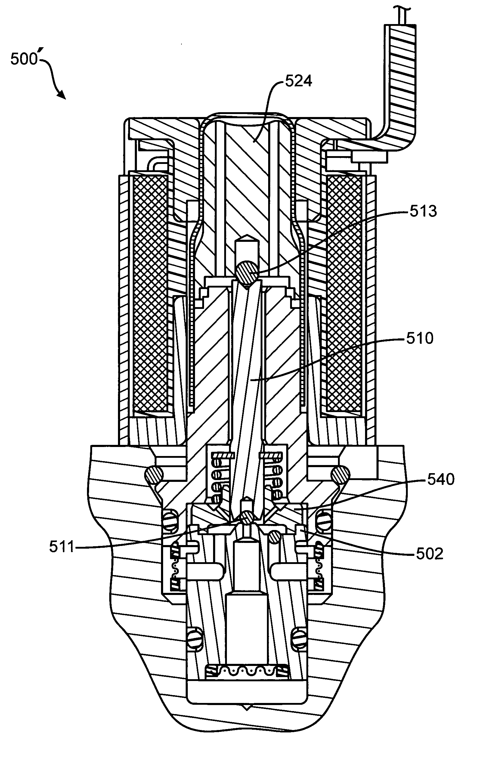
[0060]a normally closed control valve is indicated generally at 200 in FIG. 5. The control valve 200 can be used as the isolation valve 38 and / or the dump valve 44 in the brake system 10 of FIG. 1. The control valve 200 includes a seat or valve body 202 mounted in the housing 18. An adapter 204 has a lower annular flange 206 that is crimped onto the seat 202 to retain the adapter 204 thereto. An annular filter assembly 208 is fitted about the adapter 204 and seat 202.

[0061]An armature 210 is slidably disposed in a tube or sleeve 212. A ball 213 is pressed into an axial bore 214 formed in the armature 210. A cross hole 216 is formed in the armature 210 in fluid communication with the axial bore 214. A first end of a spring 218 engages an insert 220 disposed in a cavity in the armature 210. A second end of the spring 218 is fitted about an extension 222 formed on a magnetic pole member 224. A solenoid subassembly 226 is fitted over the pole member 224 and sleeve 212. Upon energization...


PUM


Abstract

A control valve includes a magnetic pole member. An armature is slidably supported relative to the magnetic pole member for movement between a fully open position and a closed position. A biasing spring is disposed between the magnetic pole member and the armature for forcing the armature away from the magnetic pole member. A coil is placed about the magnetic pole member and the armature for inducing a magnetic field for moving the armature toward the magnetic pole member. One of either of the magnetic pole member or the armature has a recess for non-contactingly receiving the other when the armature moves between the fully open and closed positions. The control valve can be embodied as a normally open valve or a normally closed valve. The use of dual lateral poles and triple lateral poles create a flat magnetic force versus travel curve thereby allowing for greater proportional control of the valve. Additionally, the use of double lateral gaps and triple lateral gaps respectively results in force increases of 21% and 12% respectively. Compounding the force increases results in a net additional force of 36%.

Description

CROSS REFERENCE TO RELATED APPLICATIONS[0001]This application claims the benefit of U.S. Provisional Application No. 60 / 325,569 filed Sep. 28, 2001 and is a Continuation-In-Part of U.S. patent application Ser. No. 09 / 465,487, filed Dec. 16, 1999 now abandoned, which in turn claims the benefit of U.S. Provisional Application No. 60 / 112,431, filed on Dec. 16, 1998.INCORPORATION BY REFERENCE[0002]The disclosures of U.S. patent application Ser. No. 09 / 465,487 filed Dec. 16, 1999 and U.S. Patent Application No. 60 / 112,431 filed Dec. 16, 1998 are hereby incorporated by reference.BACKGROUND OF THE INVENTION[0003]This invention relates in general to vehicular brake systems, and in particular to control valves for electronically controlled vehicular brake systems.[0004]Electronically controlled brake systems for vehicles are well known. A typical electronically controlled brake system includes a hydraulic control unit (HCU) connected in fluid communication between a master cylinder and a plu...

Claims


Application Information

Patent Timeline
IPC IPC(8): B60T8/36
CPCB60T8/363H01F7/1607F16K31/0665B60T8/367
Inventor KRAWCZYK, GREG J.LINKNER, JR., HERBERT L.
Owner KELSEY HAYES CO
Why Eureka
Try Eureka