Network plug

Inactive Publication Date: 2006-02-07
EXCELLENCE WIRE IND
View PDF4 Cites 34 Cited by
  • Summary
  • Abstract
  • Description
  • Claims
  • Application Information

AI Technical Summary

Benefits of technology

[0004]The present invention has been accomplished under the circumstances in view. It is therefore main object of the present invention to provide a network plug that eliminates the aforesaid drawbacks. According to one aspect of the present invention, the network plug comprises a plug body, two locking bars pivotally mounted in the top wall of the plug body, a jacket coupled to the rear side of the plug body and movable relative to the plug body in axial direction within a limited distance, and a working plate

Problems solved by technology

This design of network plug 8 is still not satisfactory in function.
This operation method requires much e

Method used


Image

  • Network plug
  • Network plug
  • Network plug

Examples


Embodiment Construction

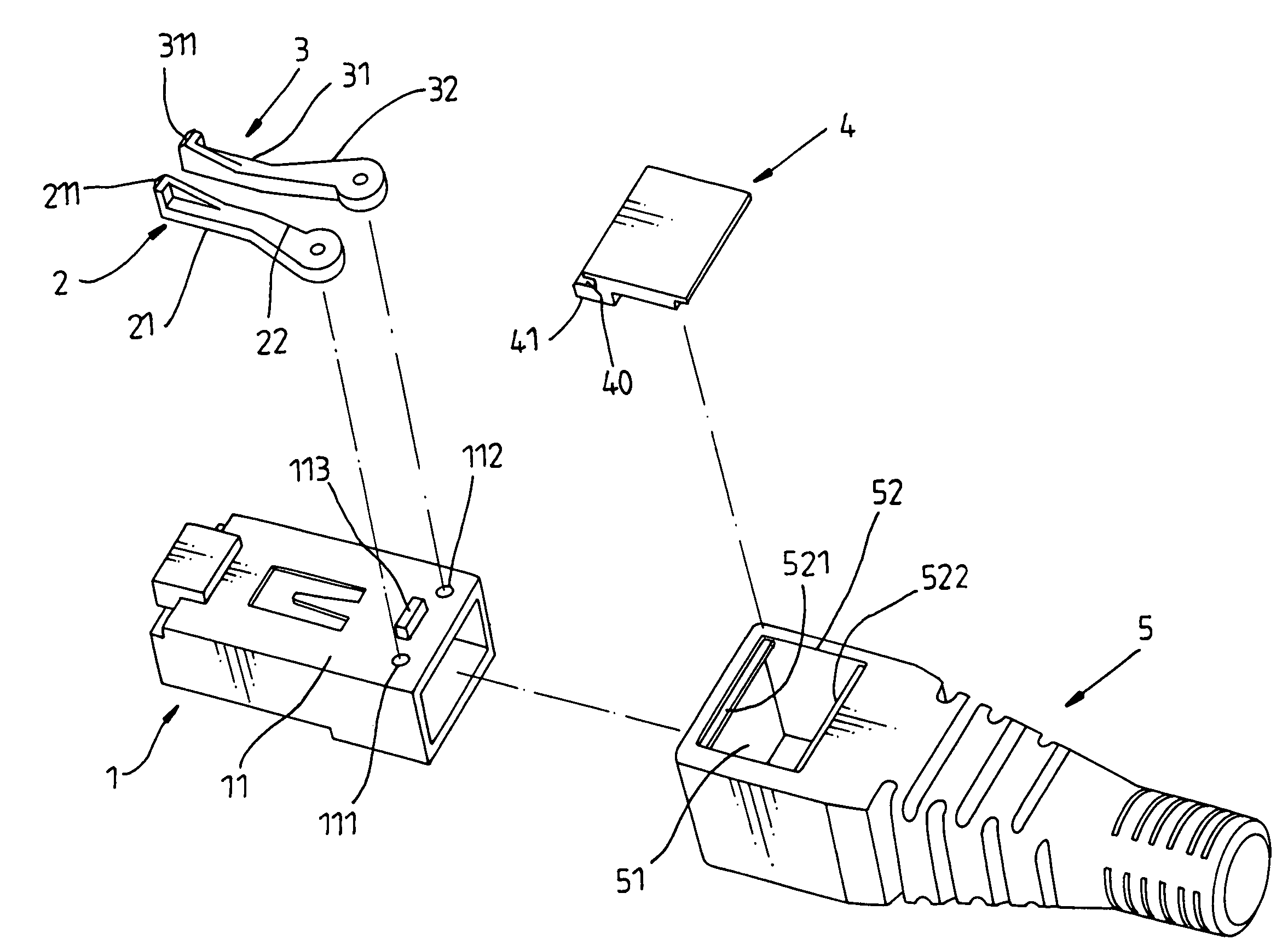
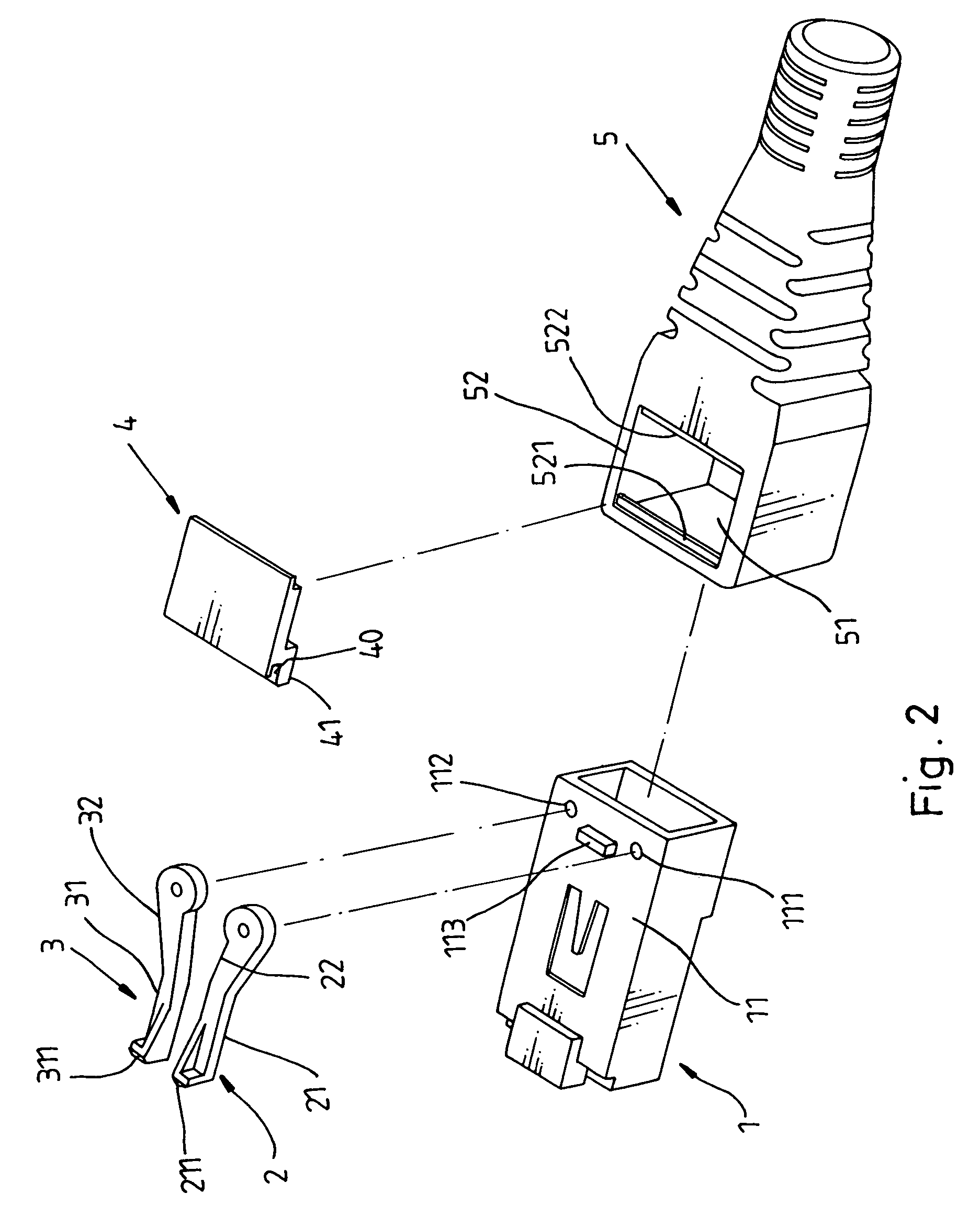
[0015]Referring to FIGS. 2 and 3, a network plug is shown comprised of a plug body 1, a first locking bar 2, a second locking bar 3, a working plate 4, and a jacket 5.

[0016]Referring to FIG. 2 again, the plug body 1 has a stop block 113 protruded from the top wall 11 thereof near the rear side, and two pivot holes 111 and 112 formed in the top wall 11 near the rear side and equally spaced from the stop block 113 at two sides.

[0017]Referring to FIGS. 4–6, the first locking bar 2 has a front working part 21 terminating in a hook 211, and a rear mounting part 22 obliquely backwardly extended from the rear side of the front working part 21 and provided with a pivot pin 221. The pivot pin 221 is pivotally inserted into one pivot hole 111 of the plug body 1.

[0018]Referring to FIGS. 4–6 again, the second locking bar 3 has a front working part 31 terminating in a hook 311, and a rear mounting part 32 obliquely backwardly extended from the rear side of the front working part 21 and provided ...


PUM


Abstract

A network plug includes a plug body, two locking bars pivotally mounted in the top wall of the plug body, a jacket coupled to the rear side of the plug body and movable relative to the plug body in axial direction within a limited distance, and a working plate mounted in the jacket and movable with the jacket relative to the plug body to move the locking bars between the locking position to lock the network plug to a network socket, and the unlocking position to unlock the network plug from the network socket.

Description

BACKGROUND AND SUMMARY OF THE INVENTION[0001]The present invention relates to a network plug for connection to a network socket and more particularly, to an improved structure of network plug, which uses a slide to move two locking bars between the locking position and the unlocking position to eliminate the drawbacks of conventional network plugs that use a clip for locking.[0002]FIG. 1 shows a conventional network plug 8 for use with a network socket 9. As illustrated, the network plug 8 has a springy protruding clip 81 for locking. The protruding clip 81 has two stop edges 811 at two sides. When inserted the network plug 8 into the receiving hole 91 of the network socket 9, the stop edges 811 are respectively engaged with two locating blocks 911 inside the receiving hole 91 of the network socket 9, and therefore the network plug 8 is locked to the network socket 9.[0003]This design of network plug 8 is still not satisfactory in function. Before inserting the network plug 8 into t...

Claims


Application Information

Patent Timeline
IPC IPC(8): H01R13/625
CPCH01R13/6275H01R24/64H01R13/6392
Inventor CHEN, HSIN-HUEI
Owner EXCELLENCE WIRE IND
Why Eureka
Try Eureka