Knee-joint orthesis

a knee joint and orthesis technology, applied in the field of knee joint orthesis, can solve the problems of inability to guarantee the therapeutically required correction of the leg position of the known knee joint brace, the influence of the knee joint force, and the significant adverse

Inactive Publication Date: 2006-02-07
BAUERFEIND GMBH & CO
View PDF17 Cites 52 Cited by
  • Summary
  • Abstract
  • Description
  • Claims
  • Application Information

AI Technical Summary

Benefits of technology

[0018]In order to provide the hollow pads with a suitable counter-bearing, it is advantageous to provide supporting plates, said supporting plates covering the hollow pads and each being attached to a hinged rail.

Problems solved by technology

This results in two effects: firstly, a pressure is exerted directly at the side on the knee and therefore on the pain-sensitive joint capsule; secondly, when the knee is bent, the inflatable padding must slide on the skin surrounding the knee, this, of course, being associated with friction and leading, if the brace is worn for lengthy periods of time and especially during sporting activity, to grazing of the corresponding points on the skin.
With this knee brace, it is inevitable that there will be compressive forces acting on the knee, this having a considerably adverse effect on the wearing of such a brace, particularly when the knee is moved.
Furthermore, the screw-type adjustment of the two arms of the hinged rail, accomplished via relatively short lever arms, allows a considerable elastic hysteresis of said arms, with the result that the known knee brace cannot be guaranteed to provide a reliable therapeutically required correction of the leg position.
The knee brace serves, therefore, in particular to prevent sports injuries; it is not designed to bring about a conscious correction of the longitudinal axis of the leg.

Method used


Image

  • Knee-joint orthesis
  • Knee-joint orthesis
  • Knee-joint orthesis

Examples


Embodiment Construction

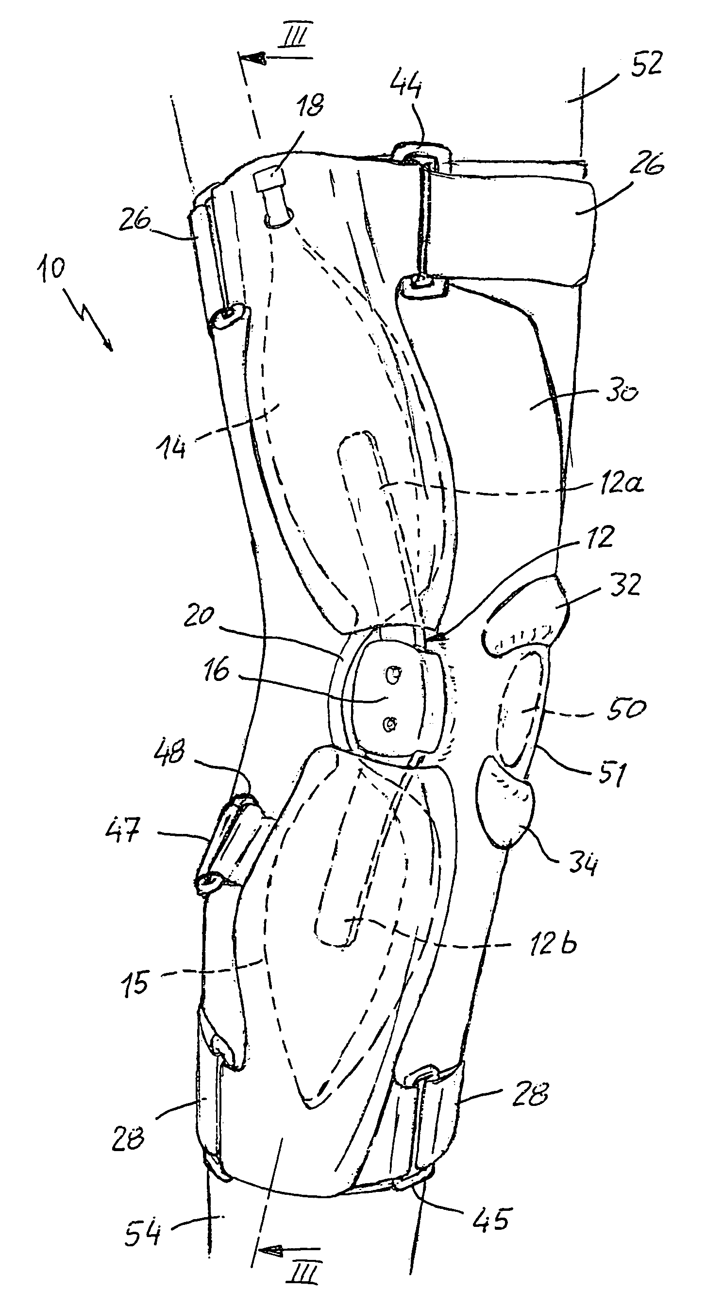
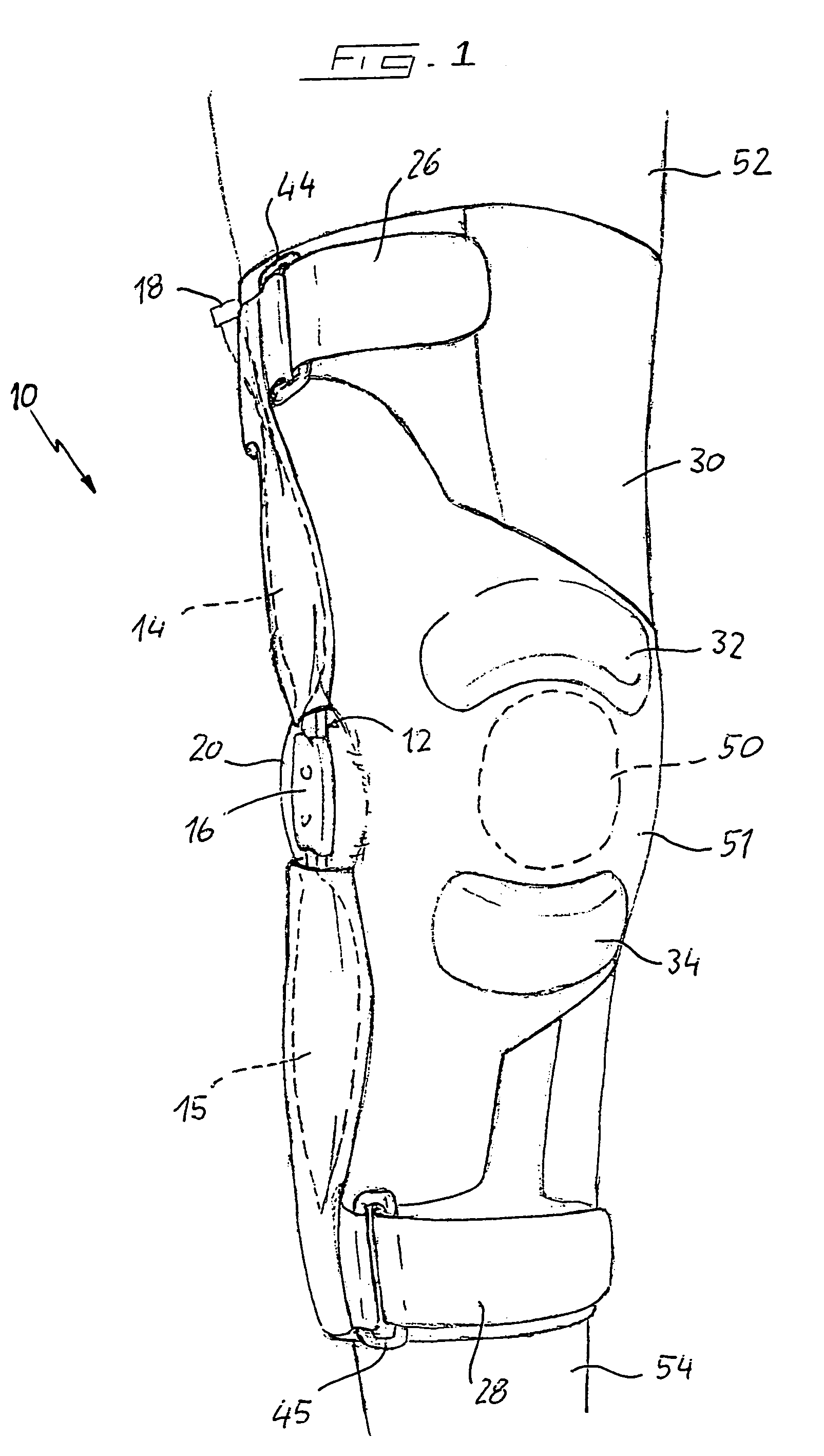
[0026]FIG. 1 shows a knee brace 10 of the first version, fitted to the upper leg 52 and lower leg 54, said knee brace 10 containing the stocking 30, said stocking 30 having been pulled over the knee 51, the position of the knee 51 being described by the patella 50 drawn with a dashed line. The knee brace 10 is tightened around the upper leg 52 by the strap 26 and around the lower leg 54 by the strap 28. The knee brace 10 is thus extensively fixed in relation to its position with respect to the upper leg 52 and lower leg 54.

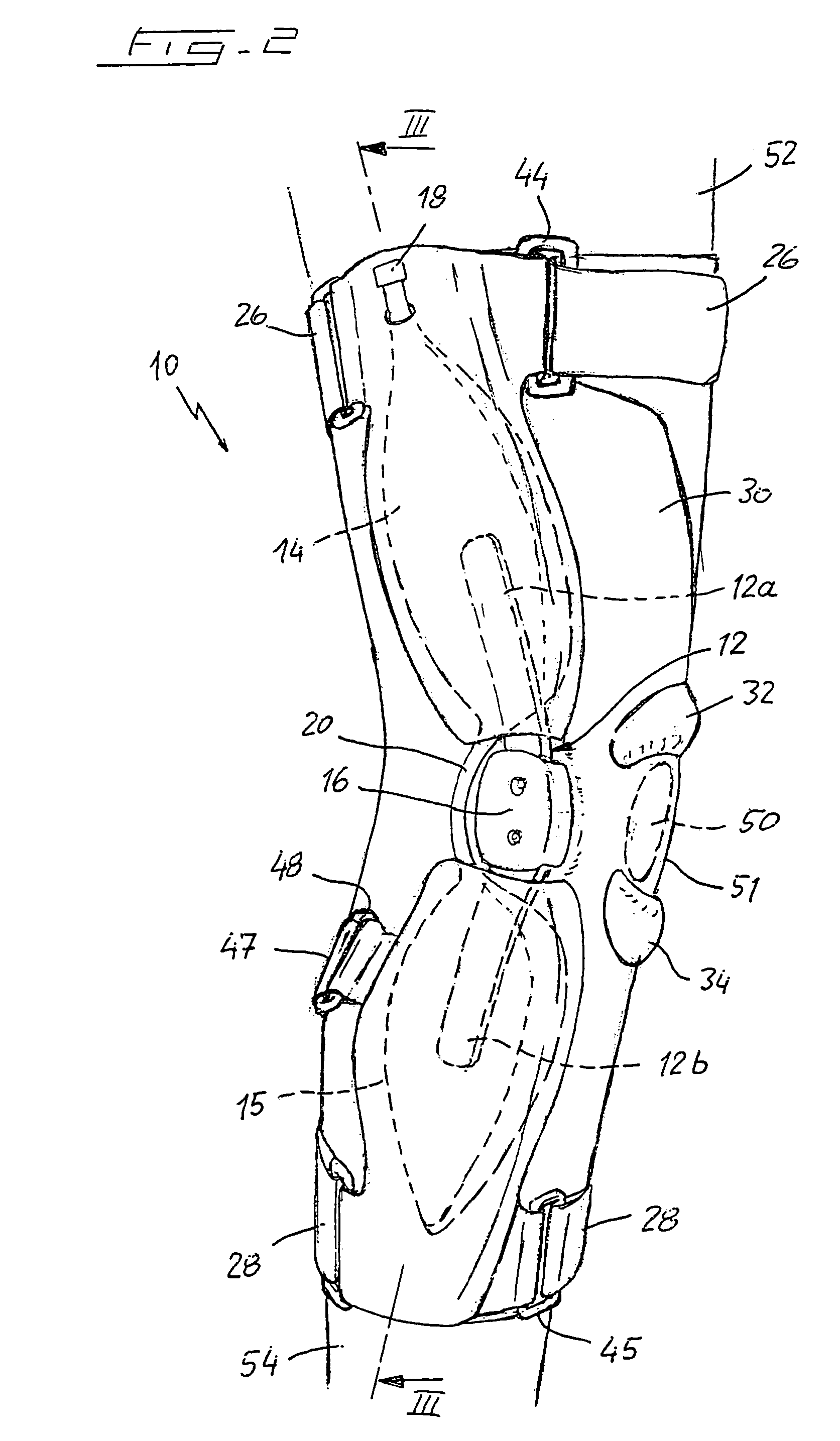
[0027]The above-named parts of the knee brace 10 are likewise presented in FIG. 2, which shows the knee brace in a side view, more specifically in a side view of the lateral side of a right knee. Incorporated into the knee brace 10 is the hinged rail 12a / 12b, which extends with its arm 12a over a portion of the upper leg 52 and with its arm 12b over a portion of the lower leg 54 and which has the hinged connection 16 in the region of the knee 51. Owing to the hing...


PUM


Abstract

The invention relates to a knee brace with straps engageable with the upper and lower leg and disposed above and below the knee, said straps being connected by a hinged rail extending over the knee at the side, said hinged rail comprising a fluid-inflatable padding and a hinged connection in the region of the knee. The padding comprises two optionally inflatable hollow pads connected by a channel, said hollow pads each being so disposed between the knee-distal straps and the hinged connection that, when the hollow pads are inflated, the knee is forced in relation to the straps into a position away from the hinged connection.

Description

[0001]The invention relates to a knee brace with straps engageable with the upper and lower leg and disposed above and below the knee, said straps being connected by a hinged rail extending over the knee at the side, said hinged rail comprising a fluid-inflatable padding and a hinged connection in the region of the knee.BACKGROUND OF THE INVENTION[0002]Such a brace is disclosed in European patent application 670 152 A1. In the known knee brace, an inflatable padding is used to correct the longitudinal axis of the leg, said padding being disposed directly at the side next to the knee and expanding through inflation such as to exert a pressure directly on the knee. Taking into consideration the position of the knee-distal straps placed around the upper leg and lower leg, the hinged rail, which extends laterally over the knee, exerts a moment on the knee, which, depending on the position of the hinged rail on the inside or outside of the leg, is thus brought towards a knock-knee positi...

Claims


Application Information

Patent Timeline
Patent Type & Authority Patents(United States)
IPC IPC(8): A61F5/00A61F5/02A61F5/01A61F5/052A61F5/058A61F5/32A61F5/34A61F13/06
CPCA61F5/0123A61F2005/0174
Inventor BAUERFEIND, HANS BREINHARDT, HOLGERSCHEUERMANN, RAINER
Owner BAUERFEIND GMBH & CO
Why Eureka
Try Eureka