Zoom lens

a zoom lens and zoom technology, applied in the field of zoom lenses, can solve the problems of difficult to simulate a picture taken at the telephoto end from an image taken at the telephoto end, difficult to satisfy the demands of compactness, and inability to achieve compactness, etc., and achieve a large wide-angle of view and excellent correction of lateral color aberration.

Inactive Publication Date: 2006-02-07
FUJI PHOTO OPTICAL CO LTD
View PDF10 Cites 11 Cited by
  • Summary
  • Abstract
  • Description
  • Claims
  • Application Information

AI Technical Summary

Benefits of technology

[0005]The present invention relates to a zoom lens of simple construction with an object-side lens group including two lens components, which may be lens elements, with a large wide-angle of view, and with excellent correction of lateral color aberration even at the wide-angle end. The present invention further relates to such a zoom lens particularly suited for mounting in a digital camera or a video camera that uses a solid state image pickup element, such as a CCD, and that is compact while providing a large wide-angle of view.

Problems solved by technology

However, it is difficult to simulate a picture taken at a wide-angle from an image taken at the telephoto end.
However, in the zoom lenses described in Japanese Laid-Open Patent Application 2003-035868, the first lens group is formed of three lens components that are lens elements so that it is difficult to satisfy the demands of compactness, which are currently strong for digital cameras and video cameras.
In other words, in order to satisfy the above requirements, the requirement of obtaining excellent optical performance at the wide-angle end has resulted in the acceptance of a requirement of a minimum of three lens components that are lens elements for the object-side lens group, and using only two lens components that are lens elements, which would provide desired greater compactness, has been assumed to result in an unacceptable optical performance, including unacceptable lateral color.

Method used


Image

  • Zoom lens
  • Zoom lens
  • Zoom lens

Examples


embodiment 1

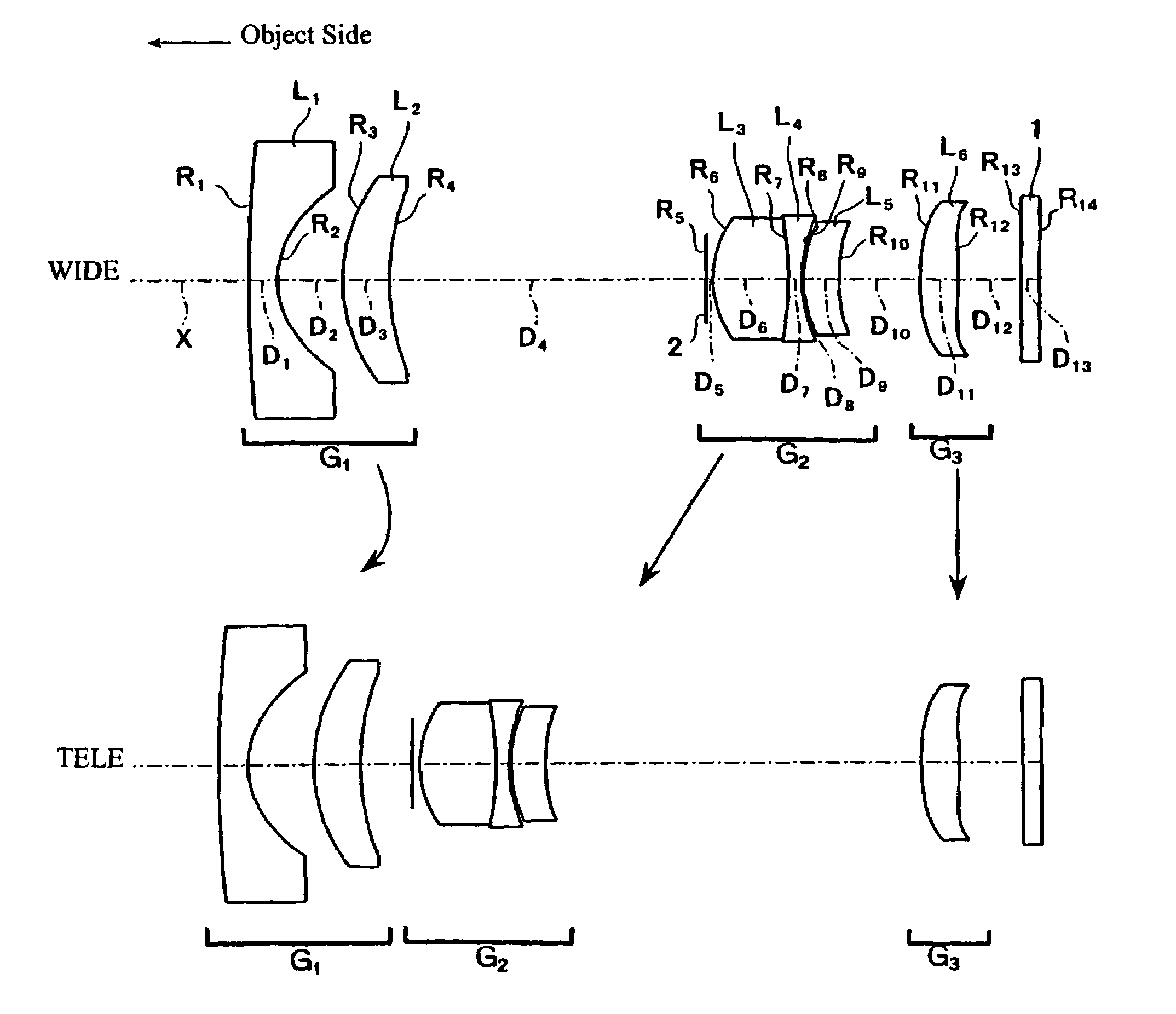
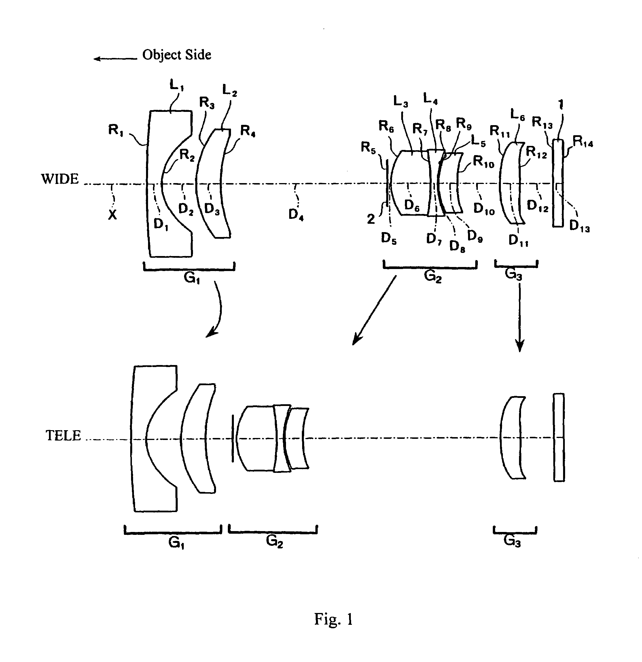
[0039]In Embodiment 1, as shown in FIG. 1, the first lens group G1 is formed of, in order from the object side, a first lens element L1 of negative refractive power and a meniscus shape with its object-side surface being convex and having a much greater radius of curvature (i.e., a much smaller curvature) than its concave image-side surface so that the first lens element L1 is nearly a plano-concave lens element, and a second lens element L2 of positive refractive power and a meniscus shape with its object-side surface being convex. Both surfaces of lens element L1 are aspheric surfaces with aspheric surface shapes expressed by Equation (A) above including both even and odd-order, non-zero terms based on both even and odd aspheric coefficients being non-zero.

[0040]The second lens group G2 is formed of, in order from the object side, a stop 2, a lens component formed of, in order from the object side, a third lens element L3 that is a biconvex lens element with its object-side surfac...

embodiment 2

[0054]Embodiment 2 is shown in FIG. 3. Embodiment 2 is similar to Embodiment 1 and therefore only the differences between Embodiment 2 and Embodiment 1 will be explained. Embodiment 2 differs from Embodiment 1 in that in Embodiment 2, the sixth lens element L6 is a meniscus lens element with its convex surface on the image side. Also, Embodiment 2 differs from Embodiment 1 in its lens element configuration by having different radii of curvature of the lens surfaces, different aspheric coefficients of the aspheric lens surfaces, some different optical element surface spacings, and two different refractive materials.

[0055]Table 5 below lists numerical values of the lens data for Embodiment 2. Table 5 lists the surface number #, in order from the object side, the radius of curvature R (in mm) of each surface on the optical axis, the on-axis surface spacing D (in mm) between surfaces, as well as the refractive index Nd and the Abbe number νd (at the d-line of 587.6 nm) of each optical e...


PUM


Abstract

A zoom lens includes at least two lens groups that move for zooming. An object-side lens group is formed of a lens component having negative refractive power and a meniscus shape and a second lens component having positive refractive power and a meniscus shape, which may be in that order from the object side. Each of these lens components may be formed of a single lens element. Lens elements of the lens components satisfy certain conditions related to the half-field angle at the wide-angle end and the Abbe numbers of the lens elements. The zoom lens may include a third lens group, which may be stationary, with a middle lens group that moves nearer the object-side lens group and farther from the third lens group during zooming from the wide-angle end to the telephoto end. At least one surface of a lens component may be an aspheric surface.

Description

BACKGROUND OF THE INVENTION[0001]Conventionally, zoom lenses for various cameras are formed, for example, of a three-group construction and include, in order from the object side, a first lens group having negative refractive power, a second lens group having positive refractive power, and a third lens group having positive refractive power. Zoom lenses with this construction have been widely used in order to produce a compact zoom lens with good correction of aberrations. For digital cameras and video cameras that have been widely used in recent years, as with zoom lenses for camera use in general, a small lens that enables high picture quality and low distortion is desired. Additionally, it is necessary to satisfy particular conditions due to the use of a solid state image pickup element, such as a CCD.[0002]Recently, in these digital cameras and video cameras where a solid state image pickup element, such as a CCD, is used, the demand for a wider angle of view in the lens has bec...

Claims


Application Information

Patent Timeline
Patent Type & Authority Patents(United States)
IPC IPC(8): G02B15/14G02B15/177G02B15/163
CPCG02B15/177G02B15/143507
Inventor SATO, KENICHI
Owner FUJI PHOTO OPTICAL CO LTD
Why Eureka
Try Eureka