Method of using a self-adjusting printed circuit board support

a printed circuit board and self-adjusting technology, applied in the direction of workpiece holders, conductive pattern formation, manufacturing tools, etc., can solve the problem of leaving large areas of larger printed circuit boards unsupported

Inactive Publication Date: 2006-02-14
MICRON TECH INC
View PDF25 Cites 6 Cited by
  • Summary
  • Abstract
  • Description
  • Claims
  • Application Information

AI Technical Summary

Benefits of technology

[0006]A universal printed circuit board support which can fully support various sizes of printed circuit board in a ...

Problems solved by technology

Prior art tooling or supports used for holding the printed circuit board in the screen printer station are generall...

Method used


Image

  • Method of using a self-adjusting printed circuit board support
  • Method of using a self-adjusting printed circuit board support
  • Method of using a self-adjusting printed circuit board support

Examples


Embodiment Construction

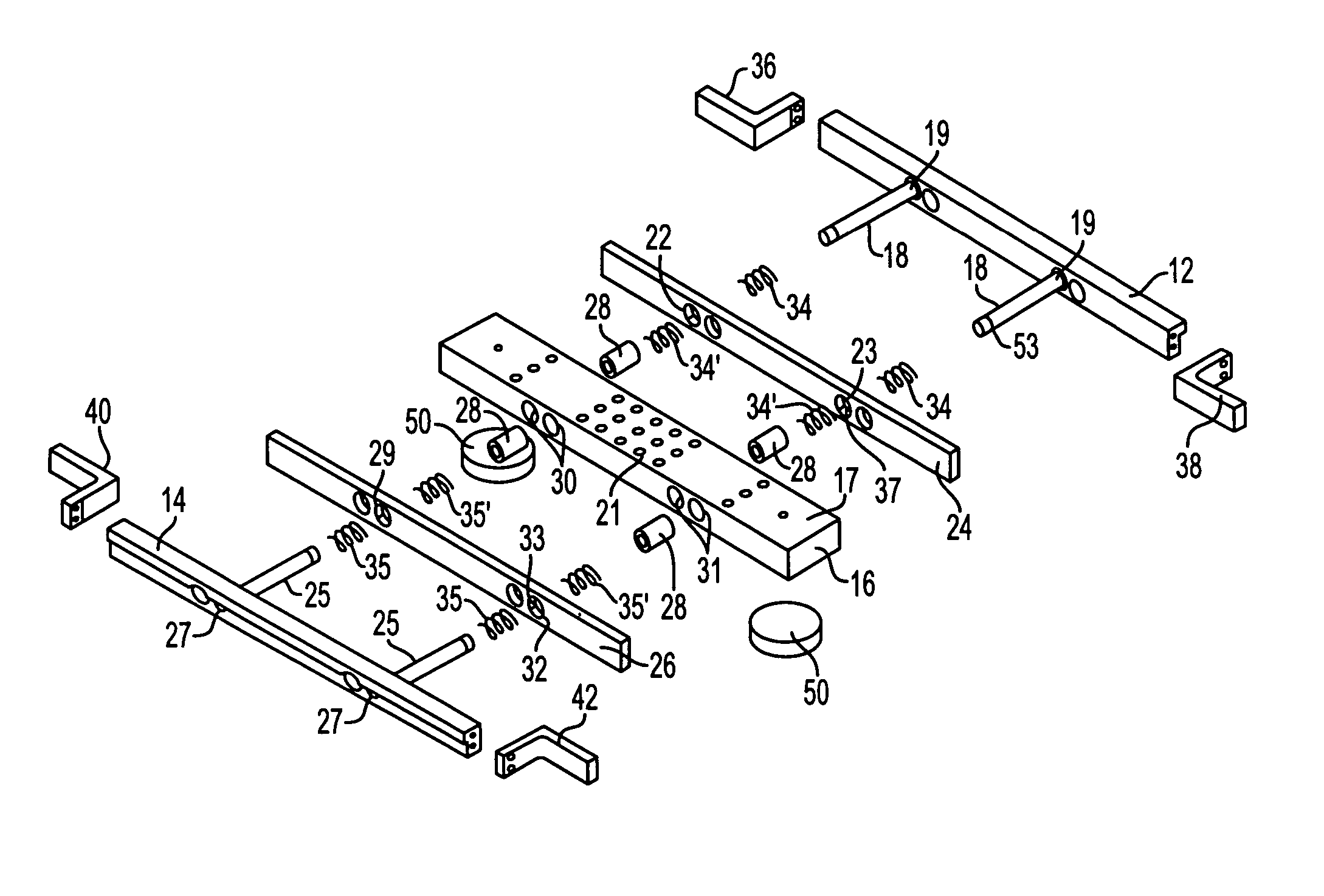
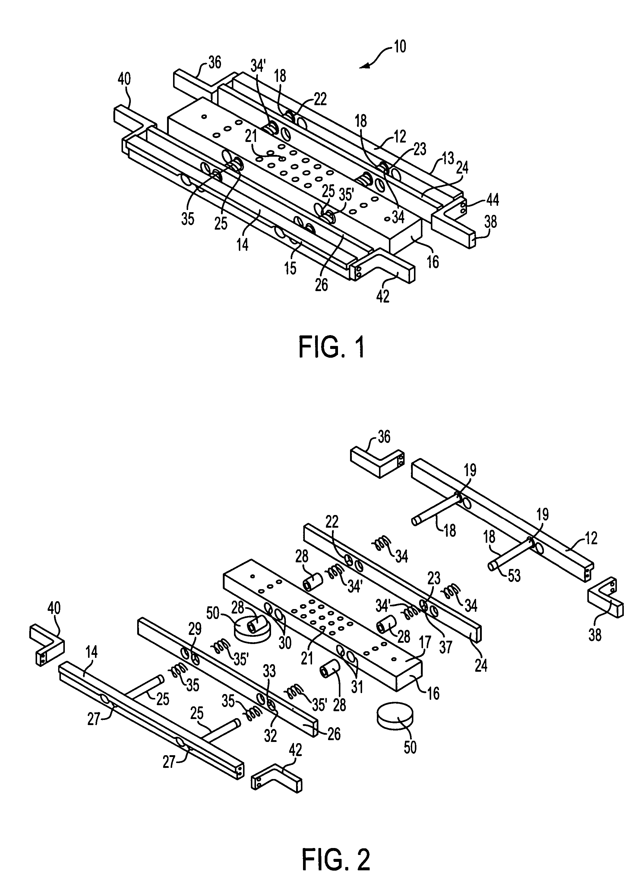
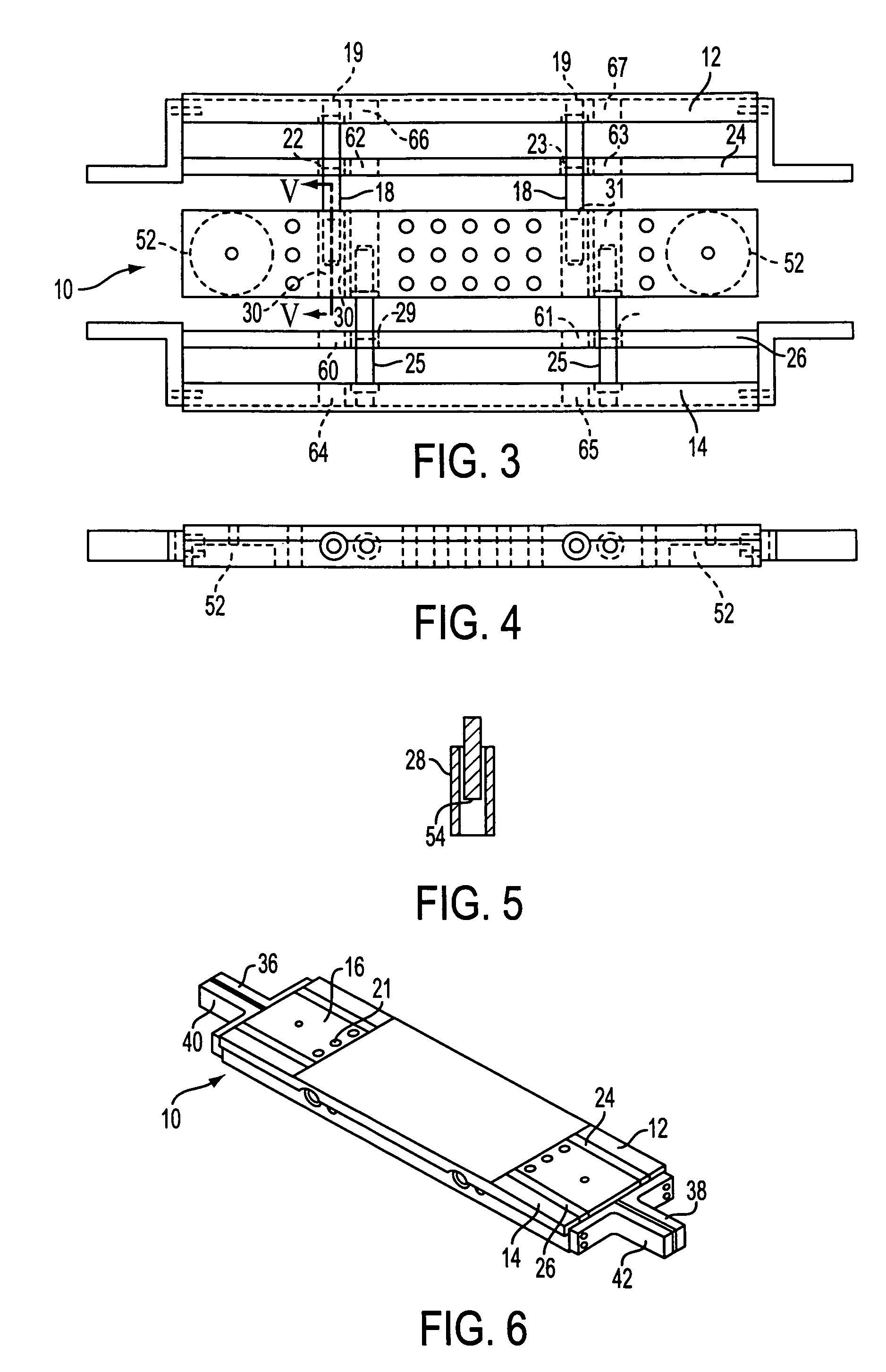
[0022]With reference to FIGS. 1–4, there is shown an embodiment of a self-adjusting printed circuit board support 10 in accordance with the present invention. The support 10 has a pair of parallel outer rails 12,14 each of which has an outwardly extending lip 13,15 for abutting engagement with a plurality of spaced surfaces 90–95 (FIG. 8) on a positioning device 97 (FIGS. 7 & 8) at an assembly station. A pair of parallel inner rails 24,26 are located between and spaced from the pair of outer rails 12,14. The support 10 also includes a mid-block 16 which is located between and spaced from the pair of inner rails 24,26. The mid-block 16 has an upper surface 17 for supporting a printed circuit board at the assembly station. Likewise, the inner 24, 26 and outer 12, 14 rails have an upper surface, co-planar with the upper surface of mid-block 16, for supporting the printed circuit board.

[0023]A pair of rods 18, each fixed at one end thereof 19 to a first one 12 of the outer rails 12,14, ...


PUM

PropertyMeasurementUnit
Timeaaaaaaaaaa
Forceaaaaaaaaaa

Abstract

A printed circuit board support including a first member having a planar upper surface for supporting a printed circuit board. At least one second member is movably coupled to a first side of the first member and movable toward and away from the side of the movable member, and a bias source biases the second member in a direction away from the first member.

Description

[0001]This application is a divisional application of U.S. patent application Ser. No. 10 / 163,380, filed on Jun. 7, 2002, now abandoned, which is continuation application of U.S. patent application Ser. No. 09 / 387,774, filed on Sep. 1, 1999, now U.S. Pat. No. 6,412,768, the entirety of which are incorporated herein by reference.BACKGROUND OF THE INVENTION[0002]1. Field of the Invention[0003]The present invention relates to a self-adjusting printed circuit board support for use at a printed circuit board screen printing station. More particularly, the present invention relates to a self-adjusting printed circuit board support for use at a screen printer station in a printed circuit board assembly line.[0004]2. Description of Related Art[0005]A common step used during the assembly of active and passive devices onto a printed circuit board is a screen printer station. Typically at this station the circuit is already on the printed circuit board and solder is squeegeed through a screen ...

Claims


Application Information

Patent Timeline
IPC IPC(8): H05K3/36H05K3/12H05K13/00
CPCH05K13/0069H05K3/1216Y10S269/903Y10T29/53261Y10T29/53961Y10T29/49124Y10T29/49133Y10T29/53191Y10T29/4913Y10T29/53265Y10T29/53913Y10T29/5313Y10T29/49126
Inventor PECKHAM, MARK VTEITENBERG, TONY
Owner MICRON TECH INC
Why Eureka
Try Eureka