Oil filtration vessel

a technology of oil filtration and oil tank, which is applied in the direction of filtration separation, moving filter element filters, separation processes, etc., can solve the problems of only suitable filtration methods, hampering the overall efficiency of the filtering system, and significant periods, and achieves the effect of convenient configuration

Active Publication Date: 2005-08-11
FILTERTECH
View PDF18 Cites 16 Cited by
  • Summary
  • Abstract
  • Description
  • Claims
  • Application Information

AI Technical Summary

Benefits of technology

[0008] It is a principal object and advantage of the present invention to provide a filter system that is easy to service.
[0009] It is an additional object and advantage of the present invention to filter system that can remain on-line during service operations.
[0010] It is a further object and advantage of the present invention to provide a filter system that is modular and can be easily configured into various sizes for different applications.
[0011] Other objects and advantages of the present invention will in part be obvious, and in part appear hereinafter. SUMMARY OF THE INVENTION
[0012] The present invention is a filter vessel comprising a frame having individual compartments, a removable filter rack in each compartment, and an array of filter elements positioned in candle housing that are moveable into and out of the filter racks. Each compartment has an independent set of dirty oil inlets, clean oil outlets, overflow outlets, and air purge inlets, and is fluidly separated from adjacent compartments by the interior walls of the frame. Each rack may be disengaged from the various pipes and removed from the frame without disengaging the racks in adjoining compartments. As a result, the filter elements may be serviced without having to take the entire system off-line.

Problems solved by technology

However, this method of filtration is only suitable for some hot mill applications.
With these filters, however, it is necessary to periodically stop filtration, remove contaminated materials, and replace the filters before going back on line.
While a supamic filter adequately filters industrial oil, the maintenance required to maintain the system results in significant periods of downtime and hampers overall efficiency of a filtering system.
Although accumulated sludge may be removed from the fiberglass filter elements by backwashing with compressed air, backwashing is not always effective and the filter elements must be periodically removed and cleaned to insure proper operation of the system.
As a result, the filter tank must be taken out of service, thereby halting or limiting the filtration capabilities of the entire system.

Method used


Image

  • Oil filtration vessel
  • Oil filtration vessel
  • Oil filtration vessel

Examples


Embodiment Construction

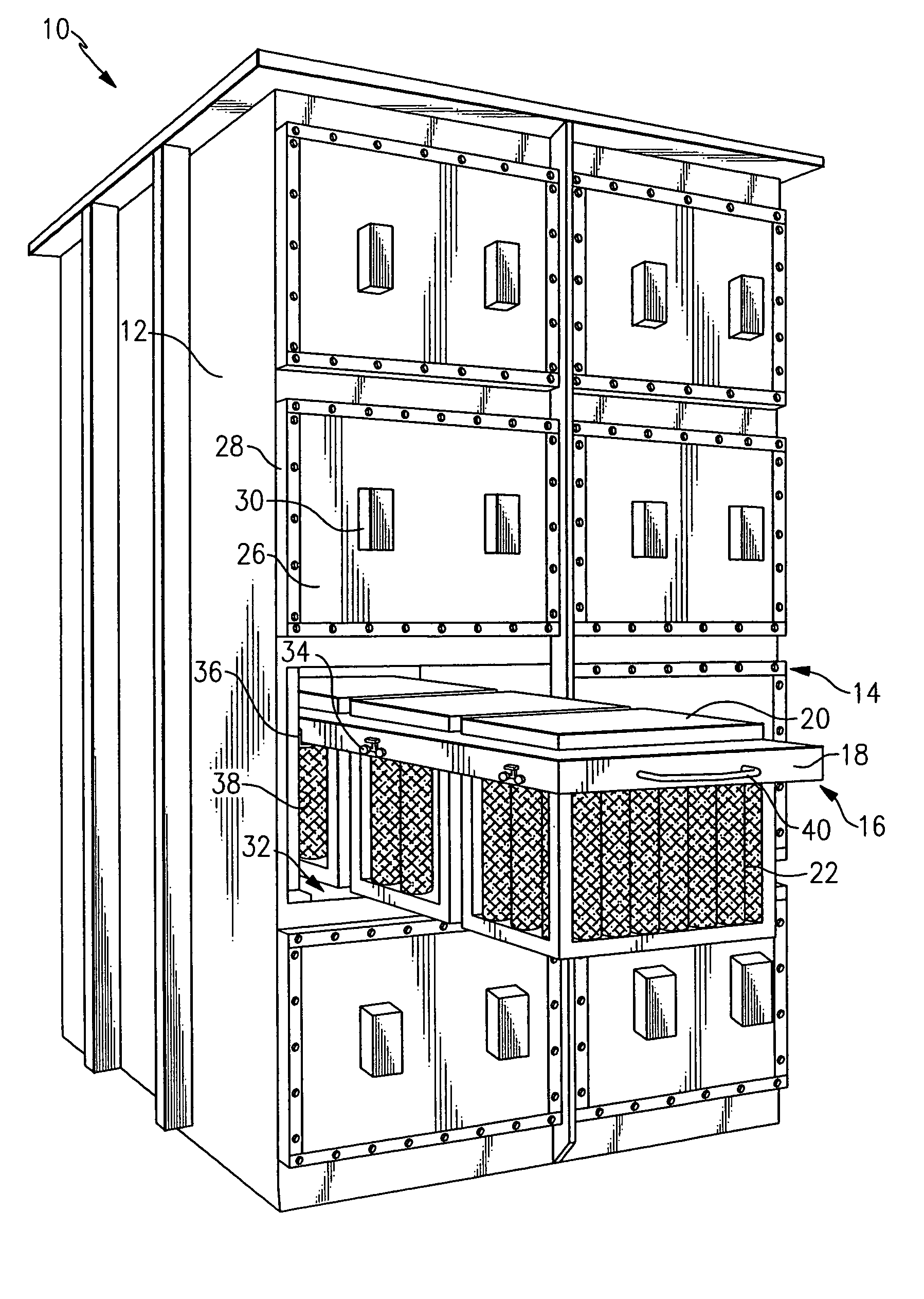
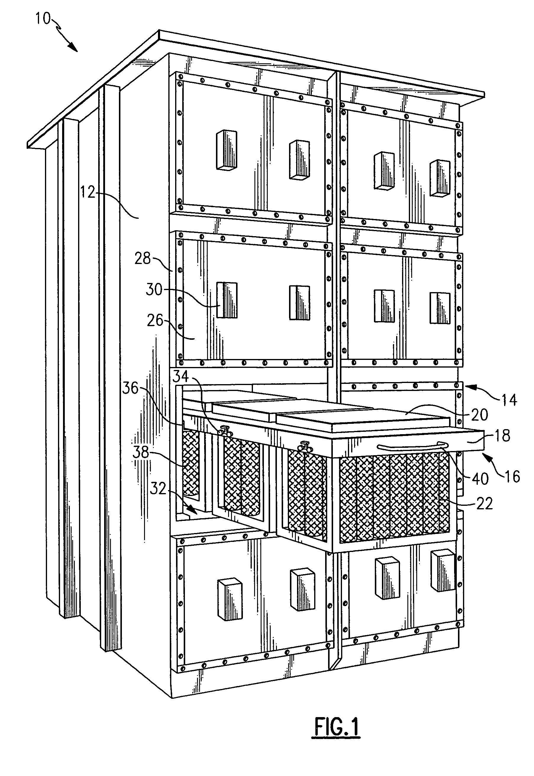
[0025] Referring now to the drawings wherein like numerals refer to like parts through, there is seen in FIG. 1 a filter vessel 10 according to the present invention. Vessel 10 generally comprises a vessel frame 12 having individual compartments 14, and a set of removable racks 16 in sliding engagement with each compartment 14. Each rack 16 includes a circumferentially extending hollow rack tube 18 that is in fluid engagement with a candle housing 20. Candle housing 20 supports an array of filter elements 22 threadably engaged to a mounting plate 24 that forms the base of candle housing 20.

[0026] The front of each compartment 14 is enclosed by a door 26 mounted securely to frame 12 via bolts 28. Each door further includes a handle 30 or other similar structure for assisting with the removal of door 26 from frame 12 after bolts 28 are removed. Each horizontal pair of rack 16 in each compartment 14 are fluidly isolated from adjoining pairs of racks 16 via the interior compartment div...


PUM

PropertyMeasurementUnit
permeableaaaaaaaaaa
lengthaaaaaaaaaa
gravityaaaaaaaaaa

Abstract

A filter system having individual compartments, a removable filter rack in each compartment, and an array of filter elements positioned in candle housing that are moveable into and out of the filter racks. Each compartment has an independent set of dirty oil inlets, clean oil outlets, overflow outlets, and air purge inlets, and is fluidly separated from adjacent compartments by the interior walls of the frame. Each rack may be disengaged from the various pipes and removed from the frame without disengaging the racks in adjoining compartments. As a result, the filter elements may be serviced without having to take the entire system off-line.

Description

BACKGROUND OF THE INVENTION [0001] 1. Field of Invention [0002] The present invention relates to industrial oil filtration systems and, more specifically, to an improved filter system having filter elements that can be serviced while other portions of the system remain at least partially online. [0003] 2. Description of Prior Art [0004] Oil filtration vessels are useful in industrial applications, such as hot and cold rolling mills, because oil cleanliness is directly related to quality of the final product. The degree and type of filtration required influences the design of the complete system. Some conventional filter systems may use paper media filter over a reservoir tank. Oil is pumped onto the filter media from where it falls into a reservoir tank. However, this method of filtration is only suitable for some hot mill applications. Other conventional filter systems use pre-coat type filters having a candle or pressure plate design. The filter is normally composed of various ble...

Claims


Application Information

Patent Timeline
Patent Type & Authority Applications(United States)
IPC IPC(8): B01D29/15B01D35/30
CPCB01D29/15B01D35/301B01D29/52
Inventor EL-HINDI, JOSEPH
Owner FILTERTECH
Why Eureka
Try Eureka