Cable support bracket

a technology of support brackets and cables, which is applied in the installation of lighting conductors, curtain suspension devices, electrical apparatus casings/cabinets/drawers, etc., can solve the problems of significant cumulative time required to install clips for all of the cables running to and from all of the junction boxes in the wiring installation, and the installation of such clips can substantially increase the labor cost associated with the installation of electric utilities in the building, so as to reduce the cost of installation, reduce labor and associated costs, easy fix or secur

Inactive Publication Date: 2006-02-14
DENIER ELECTRIC
View PDF43 Cites 62 Cited by
  • Summary
  • Abstract
  • Description
  • Claims
  • Application Information

AI Technical Summary

Benefits of technology

[0005]The present invention provides a bracket for mounting an electrical junction box that substantially reduces the costs of installing electric utilities in a building. The electrical junction box mounting bracket of the present invention allows cables terminating in the junction box to be easily and quickly fixed or secured to the bracket a desired distance from the junction box. The electrical junction box mounting bracket of the present invention eliminates the need to separately install cable securing clips to the wall frame structure, thereby substantially reducing the labor and associated costs required to install electric utilities in a building.

Problems solved by technology

While any one clip does not take long to install, the cumulative time required to install a clip for all of the cables running to and from all of the junction boxes in a wiring installation can be significant.
Thus, the installation of such clips substantially increases the labor cost associated with the installation of the electric utilities in a building.

Method used


Image

  • Cable support bracket
  • Cable support bracket
  • Cable support bracket

Examples


Embodiment Construction

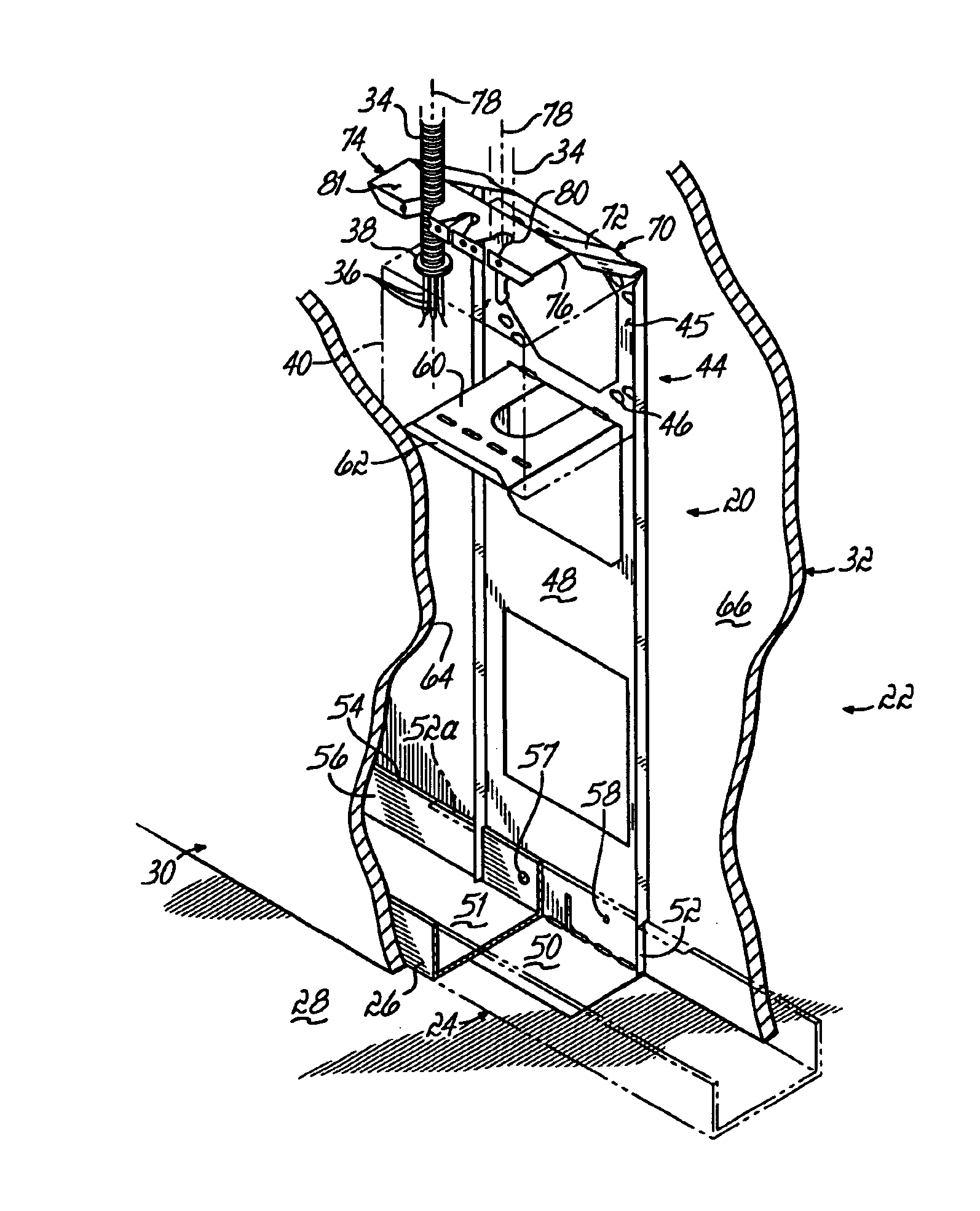
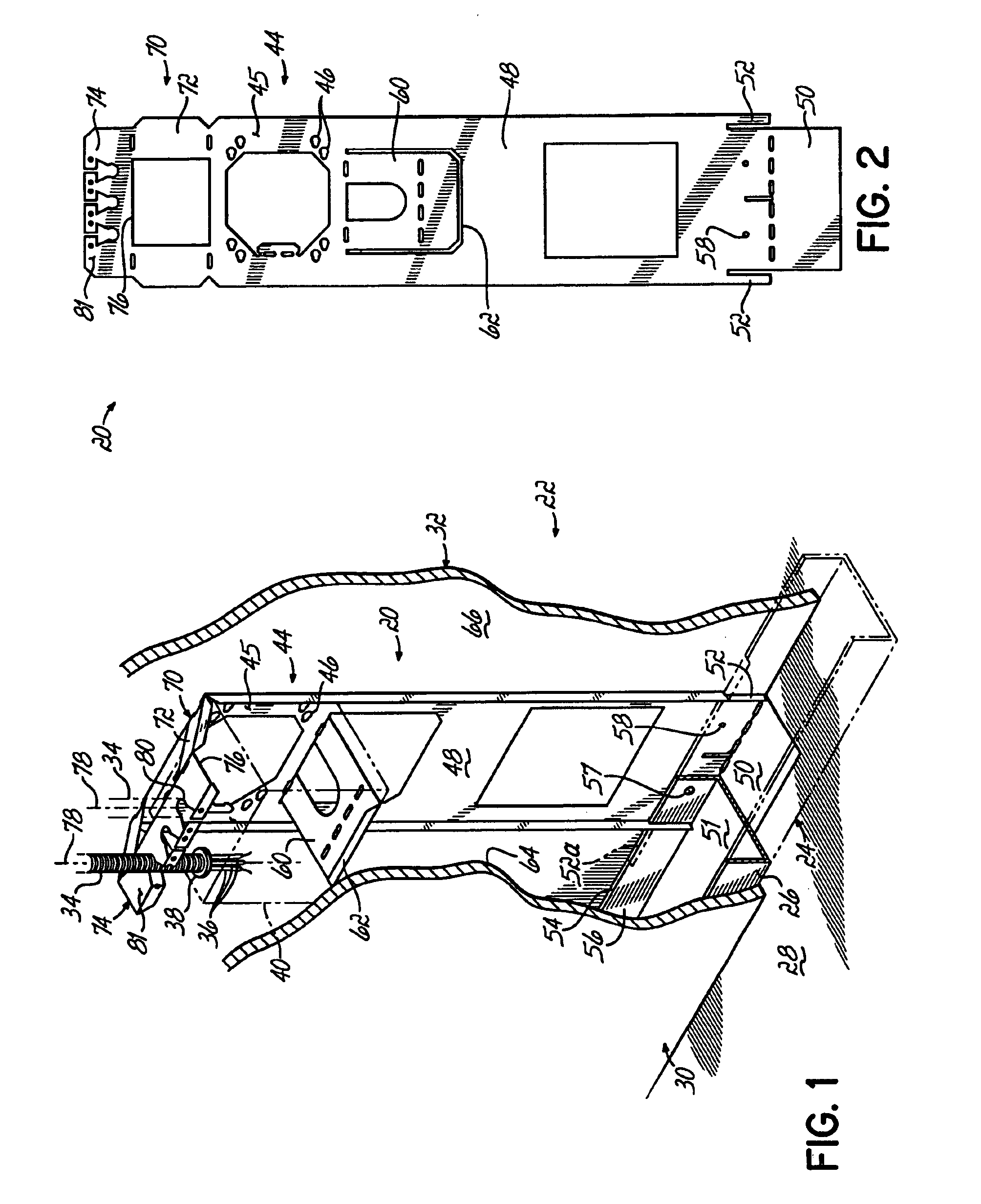
[0017]Referring to FIG. 1, an electrical junction box mounting bracket 20 is shown mounted within a wall 22. The wall 22 is made of a known wall frame structure 24 including a generally horizontal bottom track 26 that is rigidly connected to a floor surface 28. The wall frame structure 23 further includes generally vertical studs (not shown), the ends of which are rigidly connected to a generally horizontal top track (not shown) and the bottom track 26. The studs and plates are often made from an elongated generally U-shaped sheet metal channel piece. Gypsum wall board panels 30, 32 are rigidly connected to the bottom track 26 and other portions of the wall frame structure 24 in a known manner via fasteners, for example, sheet metal screws (not shown).

[0018]The bracket 20 is positioned at a desired longitudinal location with respect to the bottom track 26. Such a junction box 40 is located at a desired position with respect to the wall 22. The bracket 20 has a junction box mounting ...


PUM


Abstract

A bracket for supporting an electrical junction box within a wall frame. The bracket has a junction box support portion adapted to be connectable to the electrical junction box and a cable support portion extending from the junction box support portion. The cable support portion has a cable securing portion that receives and automatically secures the electrical cables in the cable support portion, thereby fixing the electrical cables a desired distance from the junction box.

Description

FIELD OF THE INVENTION[0001]This invention relates generally to wiring accessories and more particularly, to wiring accessories for routing and securing wires in the interior of a studded wall.BACKGROUND OF THE INVENTION[0002]Known building construction utilizes a wall frame structure comprised of vertical studs interconnected with horizontal head and toe plates. Wall material like gypsum wall board is fastened to both sides of the studs and plates to provide a finished wall surface. Electric utilities, for example, power wires, communications cables and other kinds of wiring are often located in flexible, metal clad or armored cable; and the metal cable containing the wires is routed within the wall frame structure prior to the gypsum wall board being installed. In recent years, an increasing number of structures employ a metal wall frame structure rather than the traditional wooden studs and plates. A typical metal stud is an elongated U-shaped sheet metal member having a cross-se...

Claims


Application Information

Patent Timeline
Patent Type & Authority Patents(United States)
IPC IPC(8): E04C2/52E04C2/00E04B2/74H02G1/00
CPCE04B2/7457H02G1/00Y10S248/906E04B2002/7488H02G3/126
Inventor DENIER, DENNIS J.BULL, CHARLES H.KALLMEYER, JOSEPH P.
Owner DENIER ELECTRIC
Why Eureka
Try Eureka