Low-permeability connecting device

a low-permeability, connecting device technology, applied in the direction of furniture joining, building scaffolds, pipe elements, etc., can solve the problem that the entire circuit is unsuitable for complying with prescribed standards or recommendations, and the emission can achieve the effect of low-permeability coupling

Inactive Publication Date: 2006-02-14
NOBEL PLASTIQUES
View PDF13 Cites 67 Cited by
  • Summary
  • Abstract
  • Description
  • Claims
  • Application Information

AI Technical Summary

Benefits of technology

The invention offers a connection system for tubes and members where there is no leakage at all. It uses an elastic material called a sealing element that creates a tight barrier between the ends of the tubes. A special design prevents air from escaping during use. This results in better protection against unwanted substance release compared to other systems on the market.

Problems solved by technology

The technical problem addressed in this patent relates to how to effectively connect different fluids in motor vehicles through pipes and ducts while ensuring proper sealing to prevent leaks and minimize emissions.

Method used


Image

  • Low-permeability connecting device
  • Low-permeability connecting device
  • Low-permeability connecting device

Examples


Embodiment Construction

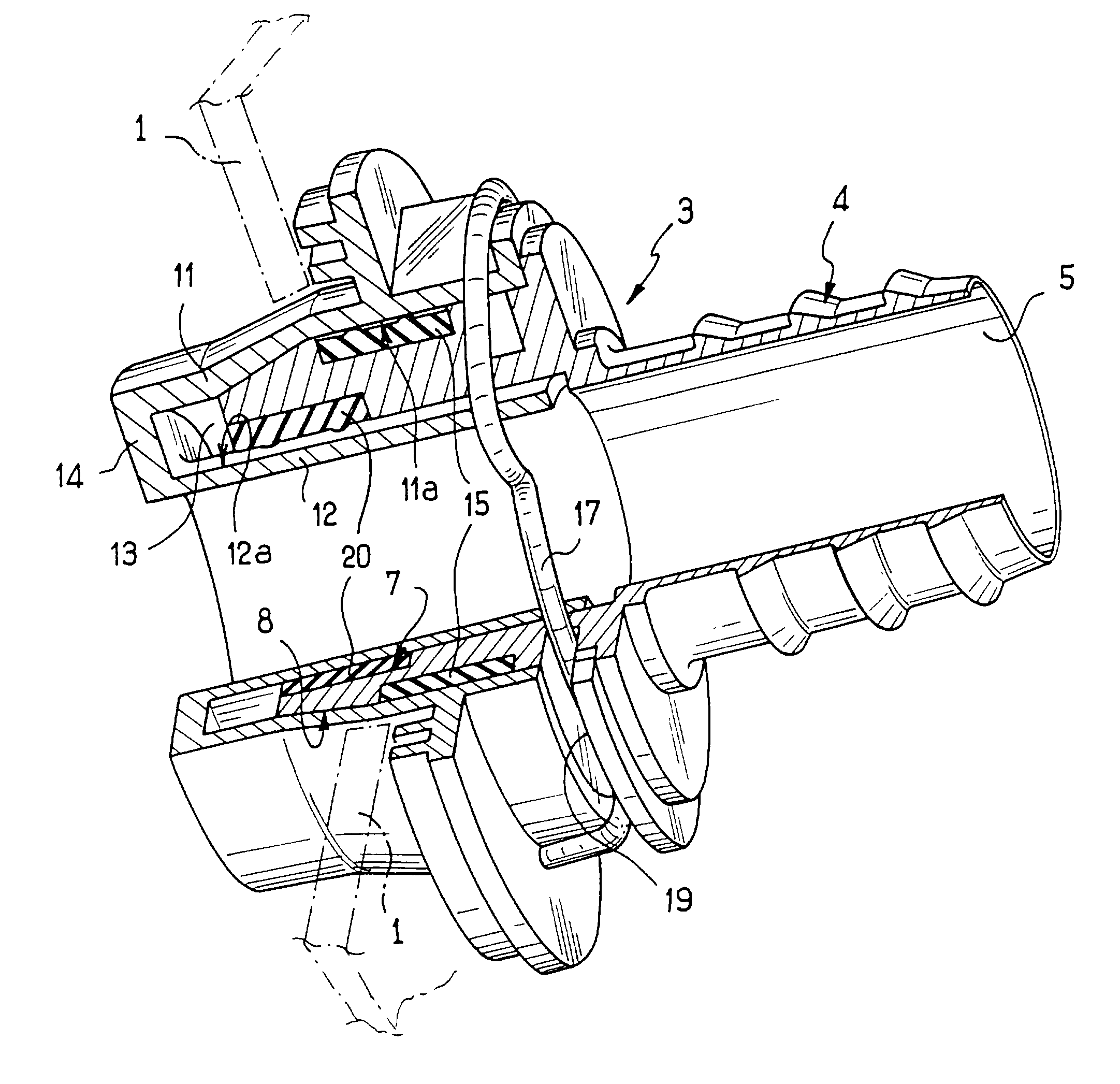
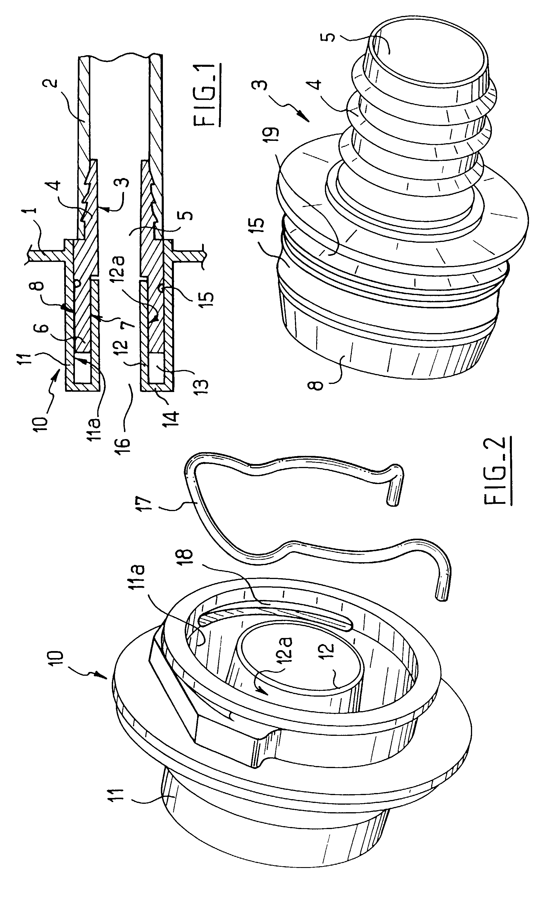
[0015]FIG. 1 shows the wall 1 of a functional member which can be, for example, a tank, a pump, . . . and which is to be connected to a tube 2. The tube 2 is extended by a rigid endpiece 3 with which it is firmly associated by any conventional device such as forced engagement on a serrated spigot 4 as shown.

[0016]The endpiece 3, which naturally has an axial inside passage 5, is terminated remote from the spigot 4 by an annular wall 6 defined by an inside surface 7 and an outside surface 8. The surfaces 7 and 8 are shown here as being coaxial about the central passage 5 of the endpiece, however the endpiece could constitute a bend with its surfaces extending differently relative to the passage.

[0017]The wall 1 of the functional member also has an endpiece 10, which endpiece has two coaxial walls 11 and 12 defining between them a blind housing 13 for receiving the portion 6 of the endpiece 3, this housing thus being closed by an end wall 14. The inner wall 12 of the endpiece 10 posses...


PUM


Abstract

A low permeability coupling device for coupling a first endpiece (3) extending a tube (2) with a second endpiece (10) carried by the wall (1) of a member to which the tube (2) is connected, in which the second endpiece (10) has two substantially coaxial walls (11, 12) defining between them a blind annular housing (13) for receiving the first endpiece (3), and a sealing element (15) extending between the inside face (11a) of the outer wall (11) of the second endpiece and the outside surface (8) of the first endpiece when it is in place in the above-mentioned housing (13).

Description


Claims


Application Information

Patent Timeline
Owner NOBEL PLASTIQUES
Why Eureka
Try Eureka