Brake system

Inactive Publication Date: 2006-02-14
BANOCZKY BELLA +2
View PDF19 Cites 12 Cited by
  • Summary
  • Abstract
  • Description
  • Claims
  • Application Information

AI Technical Summary

Benefits of technology

[0009]The instant invention is distinguished over the known prior art in a multiplicity of ways. For example, a fitting is provided with a through channel, with the fitting provided with an inlet and an outlet that allows easy attachment to a brake line anywhere along the length of the brake line, where it extends typically from the master cylinder to the brake itself. The fitting includes a passage way which receives a housing that accommodates an accumulator. The accumulator functions as an absorber or damper and is disposed within an interior of the housing and is provided with a truncated conical shape. The

Problems solved by technology

In certain situations, brakes can be applied so severely that one or more wheels can lock up.
For example, with ABS Systems, severe pressure on the brake pedal can result in a sensation of “chatter” as the valving system diverts brake flu

Method used


Image

  • Brake system
  • Brake system
  • Brake system

Examples


Embodiment Construction

[0025]Referring to the drawings, when like numerals relate to like parts, reference numeral 10 is directed to the damping system according to the present invention.

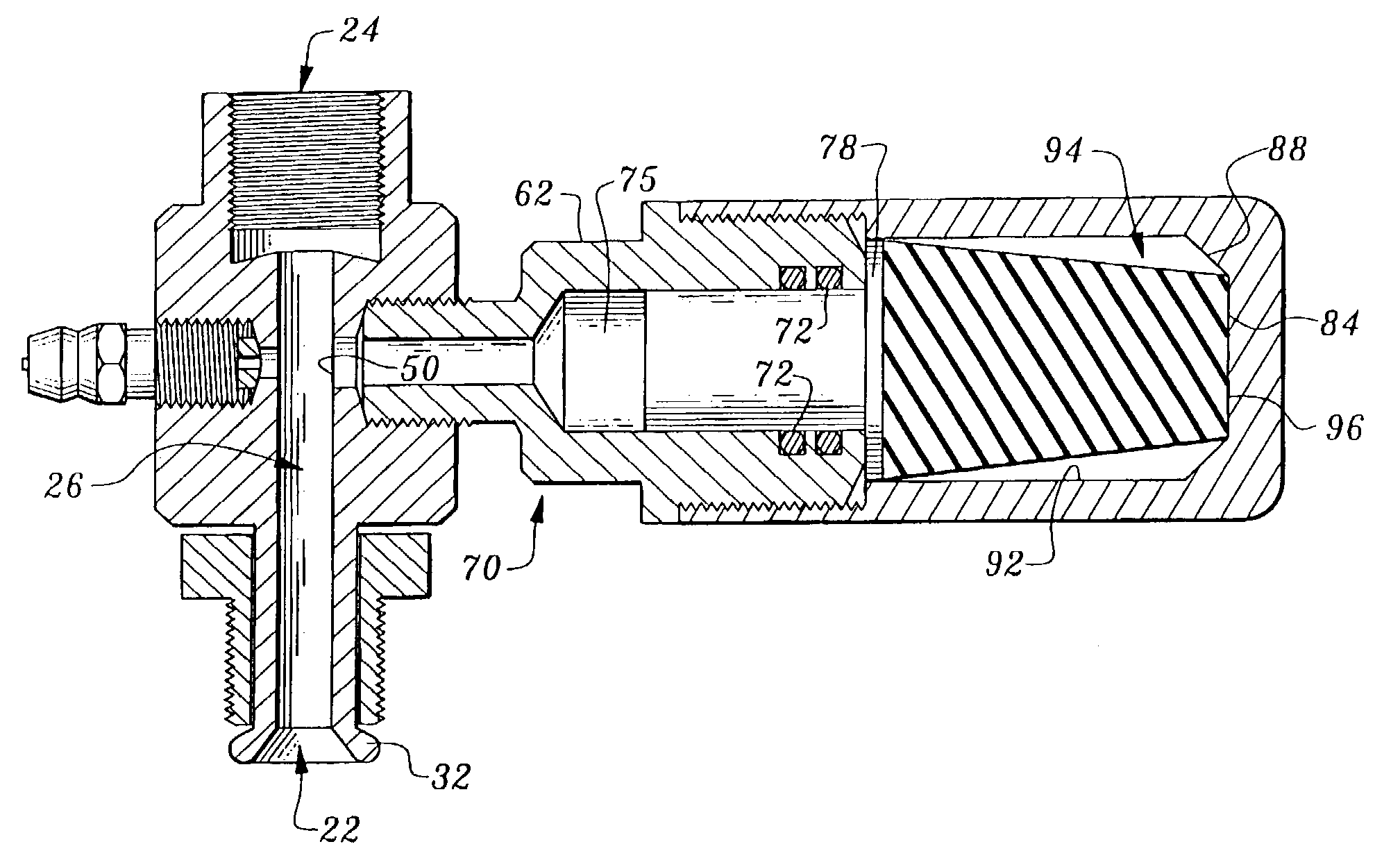
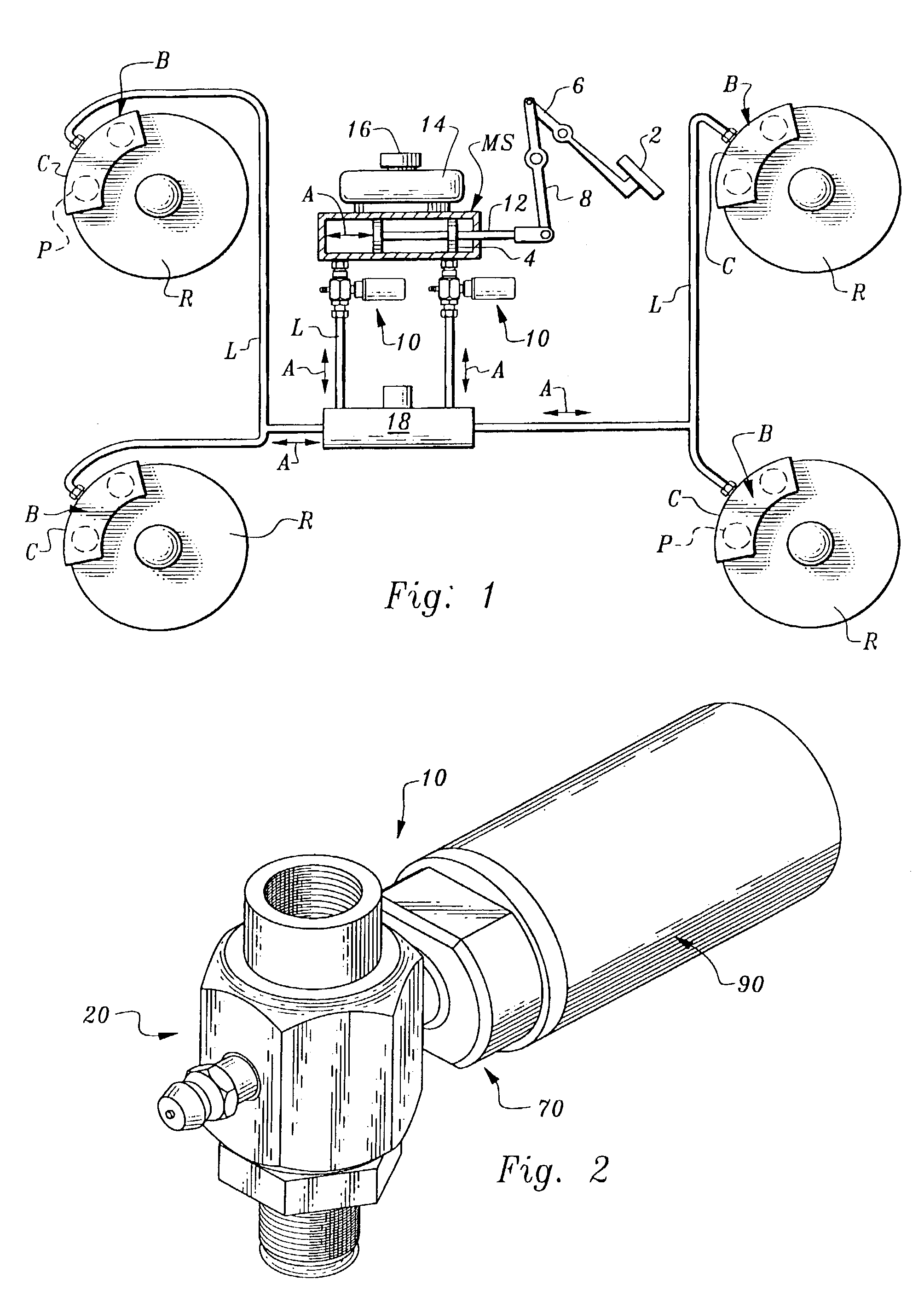
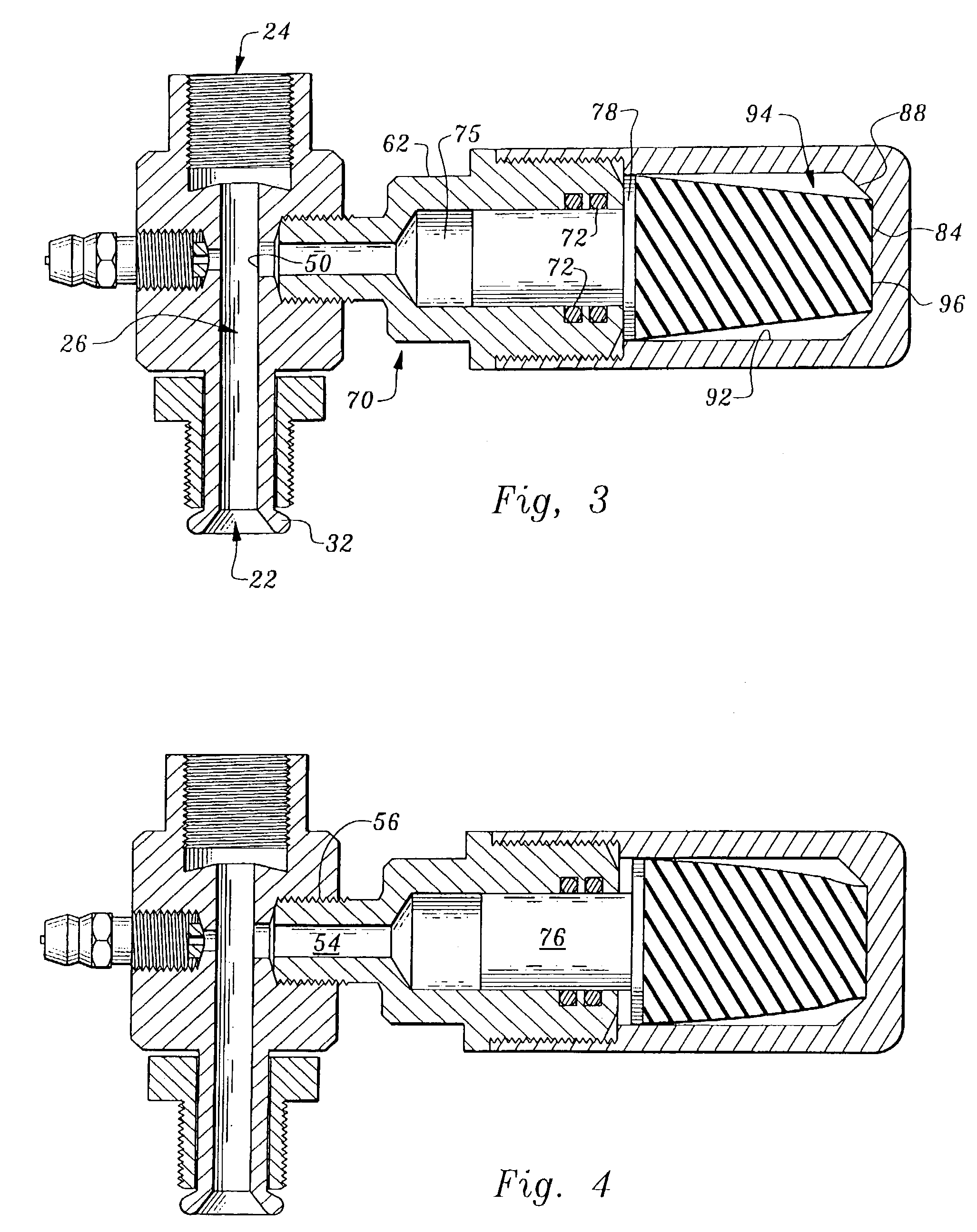
[0026]In its essence, the damping system (10) includes a fitting (20) (FIG. 2) having central channel (26) (FIG. 3) which is oriented in fluid communication with the brake fluid by its placement anywhere along the length of a brake line (L) (FIG. 1), but is most efficiently deployed adjacent the master cylinder (MS). The channel (26) includes an interior passageway (50) extending off therefrom that leads to a housing (90) (FIG. 2) within which an accumulator (80) (FIG. 5) is operatively deployed. Because the brake fluid in incompressible, shock waves transmitted through the brake fluid will arrive at the passageway (50) of the damping system (10) and be dissipated by the accumulator (80).

[0027]More particularly, and with reference to the drawing FIGS. 1 through 5, the damping system (10) is operatively deployed within the...


PUM


Abstract

A fluid damping system for brake fluid disposed in a brake line on a vehicle in which the damping system converts incompressible fluid pulses into damped energy by an accumulator which dissipates the energy to remove the pressure pulses from the fluid system.

Description

FIELD OF THE INVENTION[0001]The following invention relates generally to instumentalities used particularly for stopping the vehicle. More specifically, the instant invention is directed to a hydraulic brake system in which damping in the hydraulic circuit occurs.BACKGROUND OF THE INVENTION[0002]Hydraulic brake systems are common in the automotive world. The incompressible brake fluid extends from a brake pedal actuated master cylinder to each of the brakes located on the vehicle wheels. The master cylinder and plural slave cylinders are used in conjunction with a fluid containing brake line to distribute the flow of the brake fluid in an appropriate manner to the brakes. In certain situations, brakes can be applied so severely that one or more wheels can lock up.[0003]Although automatic brake systems have been devised which monitor whether one or more wheels have locked up and divert fluid in a rapid fashion away from the locked up brake to ensure maximum braking at times, it is co...

Claims


Application Information

Patent Timeline
IPC IPC(8): B60T17/04
CPCB60T17/04
Inventor BANOCZKY, BELLATRUEMAN, WAYNEBOHUNICKY, BERNARD P.
Owner BANOCZKY BELLA
Why Eureka
Try Eureka