Bifurcated outlet guide vanes

a guide valve and bifurcated technology, applied in the direction of machines/engines, stators, liquid fuel engines, etc., can solve the problems of reducing aerodynamic performance and engine efficiency, flow separation at excess swirl angles of exhaust, and insufficient aerodynamic profile and angular orientation of ogvs

Inactive Publication Date: 2006-02-14
NAVY DEPT OF THE
View PDF9 Cites 32 Cited by
  • Summary
  • Abstract
  • Description
  • Claims
  • Application Information

AI Technical Summary

Problems solved by technology

In applications containing large swirl range, the specific aerodynamic profile and angular orientation of the OGVs may be insufficient to prevent flow separation from the vanes at one or both extremes in the range of swirl angles.
Since a vane is typically optimized for a specific design point, off-design point operation of the vane changes the aerodynamic performance thereof eventually leading to flow separation at excess swirl angles of the exhaust.
Flow separation of the exhaust flow from the OGVs is undesirable since it destroys the ability of the vanes to properly deswirl the exhaust flow, and therefore reduces aerodynamic performance and efficiency of the engine.
The ability to deswirl exhaust flow is made more difficult in variable cycle gas turbine engines such as those specifically configured for short takeoff and vertical landing (STOVL) operations.
Performance of the turbine OGVs is further complicated by the modification of the turbofan engine for the STOVL operation which may include an extension of the fan drive shaft for powering an auxiliary fan mounted in the aircraft wing for enhancing vertical lift.
In conventional takeoff and landing operation of the engine, the swirl angle of the exhaust flow is limited in value and range.
The typical fixed-design deswirling outlet guide vane is thusly severely limited in its ability to handle the large range of swirl angle change found in a STOVL aircraft engine.

Method used


Image

  • Bifurcated outlet guide vanes
  • Bifurcated outlet guide vanes
  • Bifurcated outlet guide vanes

Examples


Embodiment Construction

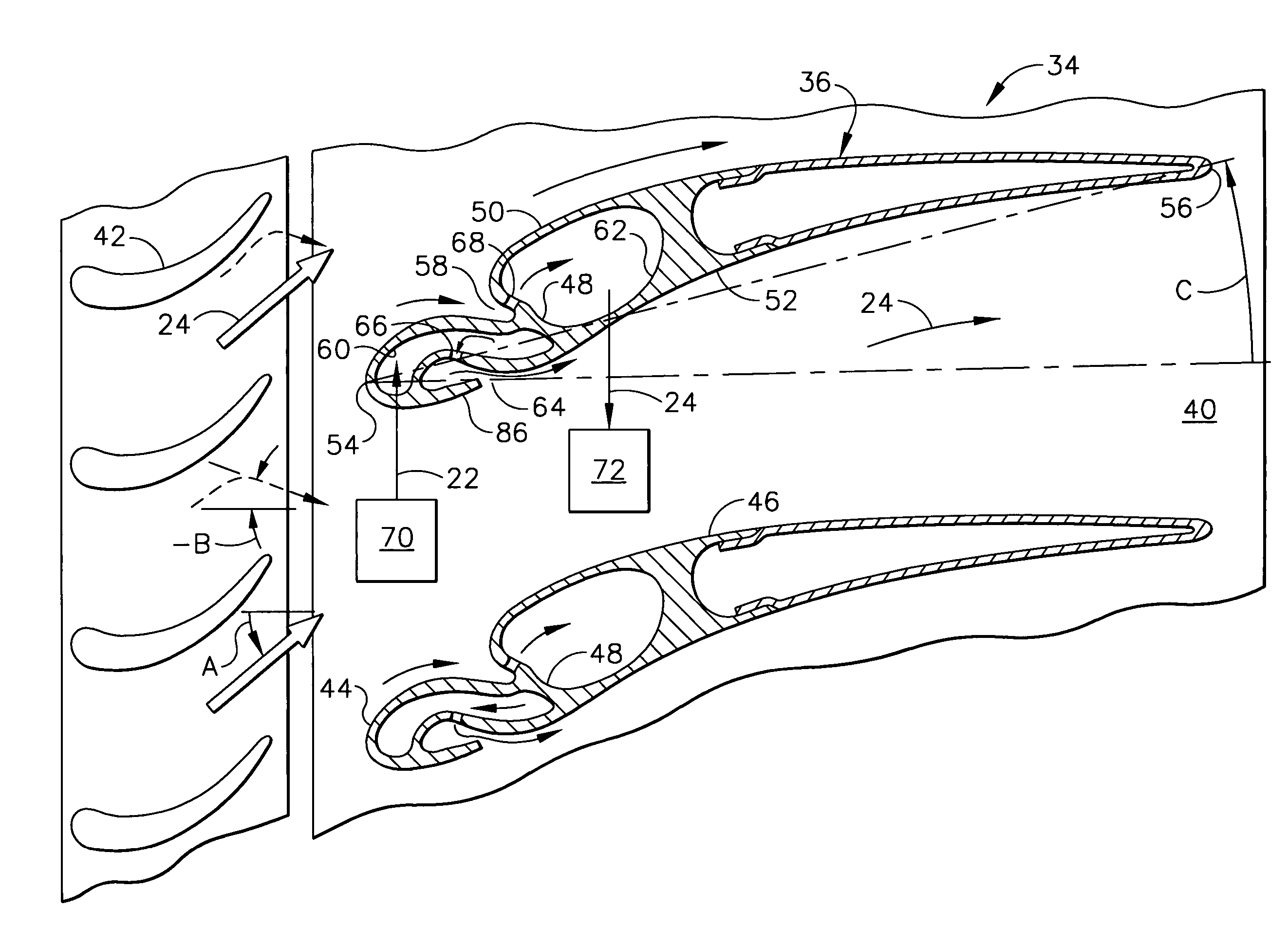
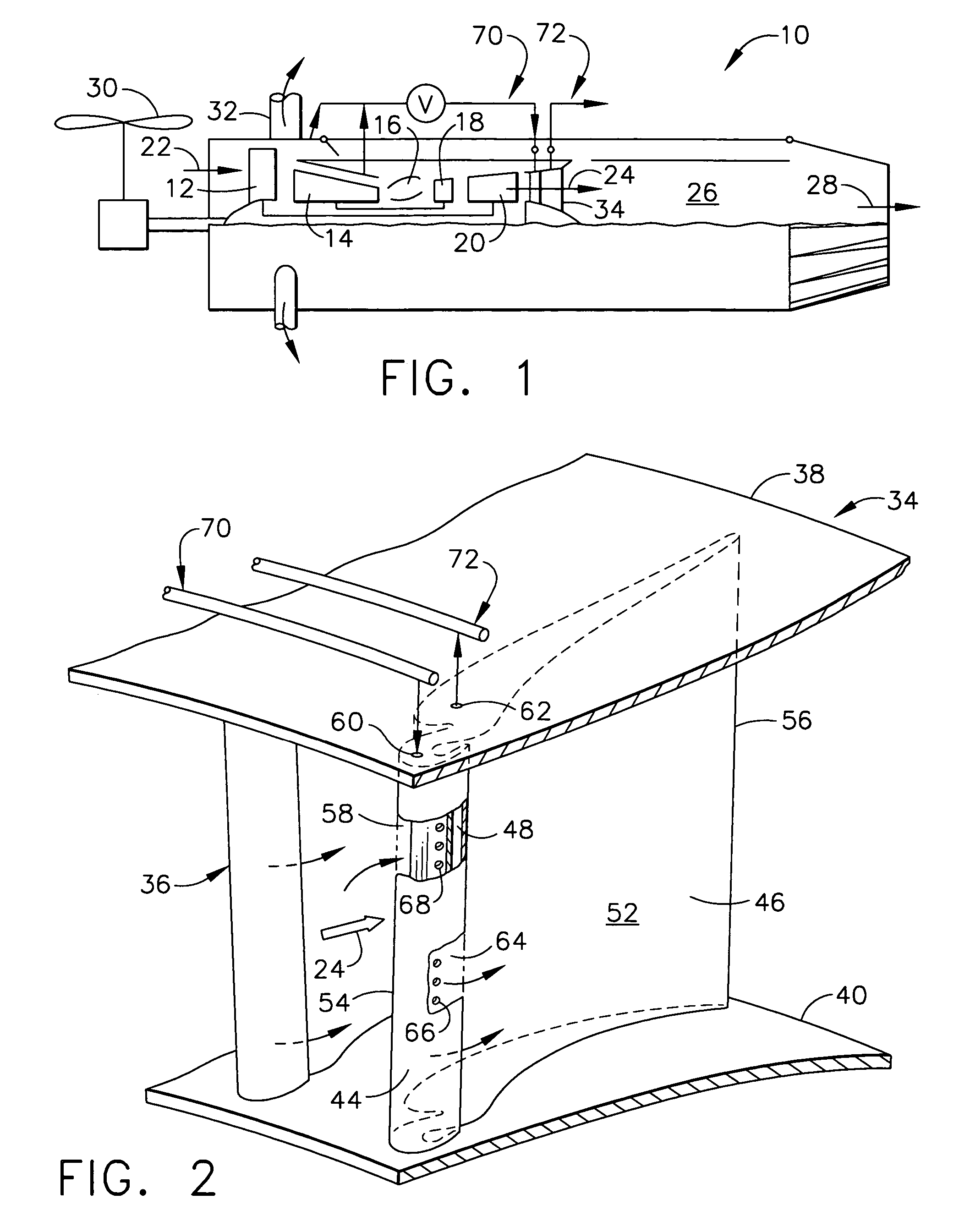
[0024]Illustrated schematically in FIG. 1 is a turbofan gas turbine engine 10 specifically configured for powering a STOVL aircraft in an exemplary application. The engine is axisymmetrical about a longitudinal or axial centerline axis and includes in serial flow communication a fan 12, multistage axial compressor 14, combustor 16, high pressure turbine (HPT) 18, and low pressure turbine (LPT) 20. The HPT 18 is joined to the compressor 14 by one shaft, and the LPT 20 is joined to the fan 12 by another shaft.

[0025]During operation, air 22 enters the engine and is pressurized in the compressor 14 and mixed with fuel in the combustor 16. The aspirated air is ignited for generating hot combustion gases 24 which are discharged in turn through the HPT 18 and LPT 20 that extract energy therefrom. The HPT powers the compressor, and the LPT powers the fan.

[0026]In the exemplary STOVL configuration illustrated in FIG. 1, the engine also includes an augmentor or afterburner 26 in which additio...


PUM


Abstract

A turbine rear frame includes a row of outlet guide vanes extending between outer and inner bands. Each of the vanes is bifurcated into a forward prow integrally joined to an aft stern by a septum therebetween. The prow and stern collectively define the aerodynamic profile of each vane which is locally interrupted at the septum.

Description

[0001]The U.S. Government may have certain rights in this invention pursuant to contract number N00019-96-C-0176 awarded by the U.S. Department of the Navy.BACKGROUND OF THE INVENTION[0002]The present invention relates generally to gas turbine engines, and, more specifically, to outlet guide vanes therein.[0003]In a gas turbine engine, air is pressurized in a compressor and mixed with fuel for generating hot combustion gases from which energy is extracted in turbine stages. A high pressure turbine (HPT) immediately follows the combustor and extracts energy for powering the compressor. A low pressure turbine (LPT) follows the HPT and extracts additional energy from the combustion gases for powering an upstream fan in an exemplary aircraft turbofan engine application.[0004]Each turbine stage includes a row of nozzle vanes specifically configured for precisely directing the combustion gases into a cooperating row of turbine rotor blades disposed downstream therefrom. The vanes and blad...

Claims


Application Information

Patent Timeline
Patent Type & Authority Patents(United States)
IPC IPC(8): F03B3/18F01D9/02F01D5/14
CPCF01D5/146F01D5/148F05D2260/202Y02T50/675Y02T50/673Y02T50/60
Inventor KOSHOFFER, JOHN MICHAEL
Owner NAVY DEPT OF THE
Why Eureka
Try Eureka