Power inlet socket

a technology of power inlet socket and power supply device, which is applied in the direction of coupling contact member, connection contact member material, coupling device connection, etc., can solve the problems of contact or interference, inability to secure terminal space, and inevitable cost increase due to additional work procedures, so as to reduce interference of ground wire, facilitate pattern design, and eliminate the use of ground wire

Active Publication Date: 2006-02-14
SAMSUNG ELECTRONICS CO LTD
View PDF8 Cites 32 Cited by
  • Summary
  • Abstract
  • Description
  • Claims
  • Application Information

AI Technical Summary

Benefits of technology

[0015]Another aspect of the present invention is to provide a power inlet socket that eliminates the use of a ground wire so as to reduce interference of the ground wire with other parts on the substrate.
[0016]Yet another aspect of the present invention is to provide a power inlet socket that facilitates designs of patterns on the substrate by securing adequate space between terminals.
[0020]Thus, when the socket is mounted on the substrate with the ground member provided on the socket body to connect to the ground terminal, the live terminal and the neutral terminal are also mounted on the substrate, which eliminates additional wire harness work as in prior art. Further, because a ground terminal is not required to be soldered on the substrate between the live terminal and the neutral terminal, space between the live terminal and the neutral terminal can be secured so that an advantage is brought out in designing patterns on the substrate.

Problems solved by technology

However, the conventional power inlet socket with the above construction has the extra ground wire 7 in addition to the ground terminal 6 so as to stabilize the power supply and the strict standard for ground continuity test conditions, but has a problem of requiring an additional wire harness process for connecting the ground wire 7 to the ground terminal 6 and substrate 1.
Furthermore, the conventional power inlet socket uses the ground wire 7 which has a certain loop-like shape formed in a distance from the socket body and is soldered on the substrate, possibly causing a problem of contact or interference of the ground wire 7 with its neighboring parts on the substrate 1 due to movements of the ground wire 7.
Furthermore, the conventional power inlet socket has the ground terminal 6 disposed between the live terminal 4 and the neutral terminal 5 and the individual terminals are soldered on the substrate 1, which brings out difficulties in securing space for the terminals upon pattern design on the substrate since patterns for terminals are closely formed on the substrate 1.
Also, the conventional substrate 1 has semicircular openings between terminal patterns in order to secure enough space between terminal patterns, which causes an inevitable cost increase due to additional work procedures.

Method used


Image

  • Power inlet socket
  • Power inlet socket
  • Power inlet socket

Examples


Embodiment Construction

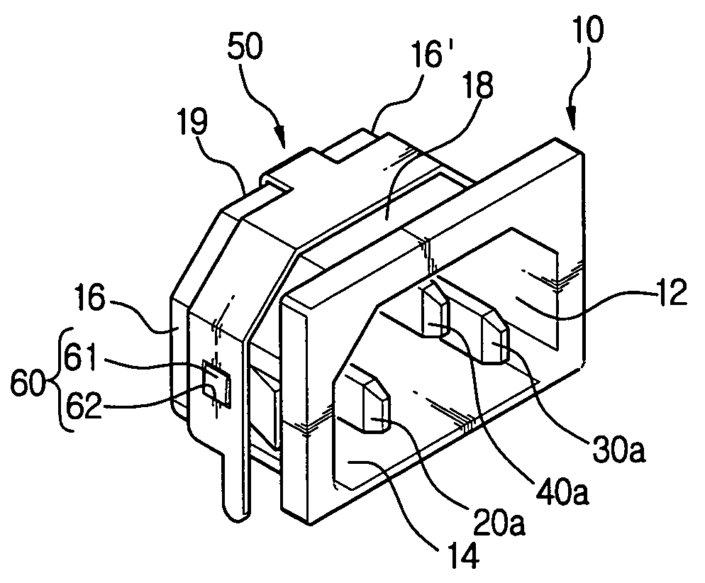
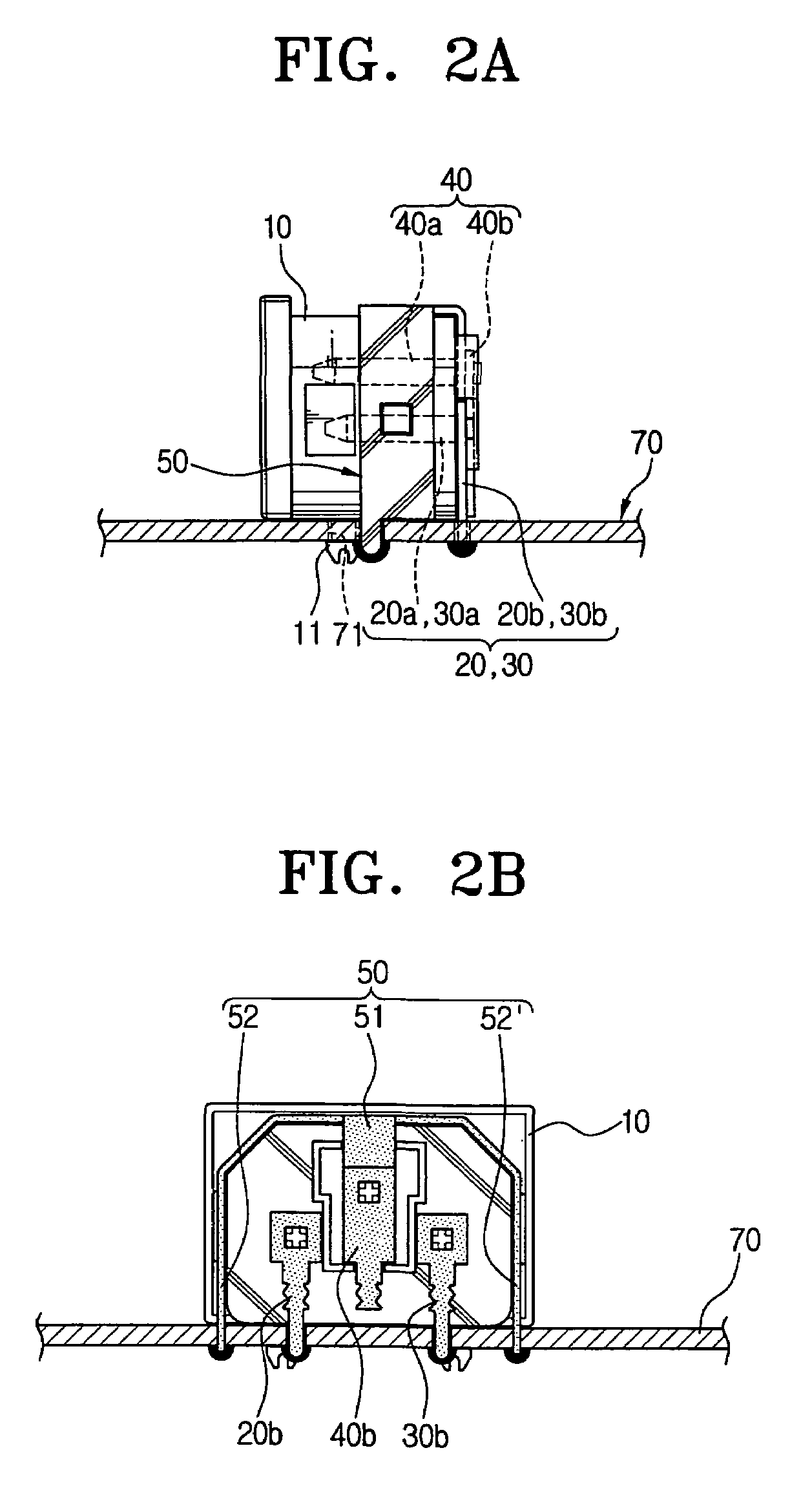
[0033]Hereinafter, illustrative embodiments of the present invention will be described with reference to the accompanying drawings. As shown in FIG. 2A, FIG. 2B, and FIG. 3, a power inlet socket has a socket body 10, a live terminal 20, a neutral terminal 30, a ground terminal 40, and a ground member 50.

[0034]The socket body 10 has a cavity 12 formed therein, defined by a bottom wall 14 in contact with a substrate 70, two opposite side walls 16 and 16′, a top wall 18, and a rear wall 19, and is open at one side thereof in order for a power plug to be externally inserted thereto. Further, the socket body 10 is preferably, but not necessarily, mounted on the substrate 70 by a pair of fixture hooks 11 that are hook-coupled into a pair of hook openings 71 formed in the substrate 70. The pair of fixture hooks 11 is formed in a middle portion of the surface of the bottom wall. Such a socket body 10 is preferably, but not necessarily, formed in a plastic mold.

[0035]A live terminal 20 and a...


PUM


Abstract

A power inlet socket includes a socket body; live and neutral terminals provided on the socket body, and each having a first pin connected to the power plug and a second pin soldered on the substrate. A ground terminal is provided between the live terminal and the neutral terminal of the socket body; and a ground member is connected to the ground terminal and soldered on the substrate at opposite sides of the socket body. The socket body has a cavity formed with a bottom wall, opposite side walls, a top wall, and a rear wall, and which is open at one side thereof. The ground member is structured to connect the ground terminal at the rear wall and is forked so as to branch from the connection to the ground terminal to surround the upper wall and the opposite side walls.

Description

[0001]This application claims benefit under 35 U.S.C. § 119 from Korean Patent Application No. 2003-82466, filed on Nov. 20, 2003, the entire content of which is incorporated herein by reference.BACKGROUND OF THE INVENTION[0002]1. Field of the Invention[0003]Apparatuses consistent with the present invention relate to a power supply device for household information appliances such as monitors, and more particularly to a power inlet socket provided on a substrate of a power supply device that is externally connected to a power plug.[0004]2. Description of the Related Art[0005]A power supply device for household information appliances has a power inlet socket to which a power plug is externally connected. Such a power inlet socket is provided on the substrate of the power supply device, and FIG. 1A and FIG. 1B are views for showing the power supply device for monitors by way of example.[0006]In FIGS. 1A and 1B, a reference number 1 denotes a substrate, and a reference number 2 denotes ...

Claims


Application Information

Patent Timeline
Patent Type & Authority Patents(United States)
IPC IPC(8): H01R13/648H01R13/652
CPCH01R13/648H01R24/78H01R12/716H01R12/707H01R2103/00
Inventor LEE, SEUNG-EON
Owner SAMSUNG ELECTRONICS CO LTD
Why Eureka
Try Eureka