
Catch basin filter

a catch basin and filter technology, applied in the field of filters, can solve the problems of waste of resources, waste of resources, waste of resources, etc., and achieve the effect of reducing the number of support devices, reducing the cost of support devices, and saving resources

Inactive Publication Date: 2006-02-14
A PAGE
View PDF10 Cites 31 Cited by
  • Summary
  • Abstract
  • Description
  • Claims
  • Application Information

AI Technical Summary

Problems solved by technology

When the bag is emptied the filter bag is further pulled down into the grate risking the spilling of solids into the basin and the contamination of the sewer line.
This is an unnecessary expense in the manufacturing of the filter bag flaps, and materials, and labor.
Other filter bags which are below the grate and inside the catch basin require expensive support devices.
In U.S. Pat. Nos. 6,149,803 and 5,849,198, the catch basin filter requires complex framing and supports which are unnecessary and expensive to manufacture, ship, and install.
These devices are unnecessary and expensive to manufacture and ship, and labor intensive to install.

Method used


Image

  • Catch basin filter
  • Catch basin filter
  • Catch basin filter

Examples


Embodiment Construction

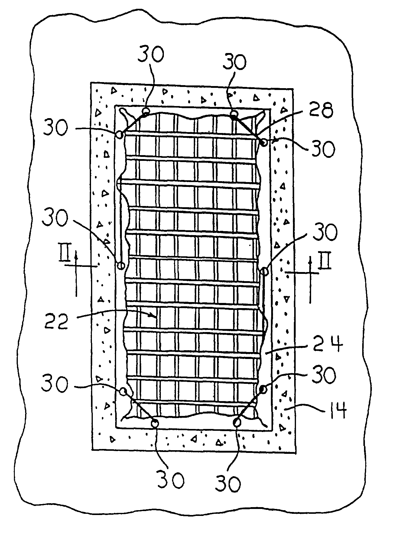
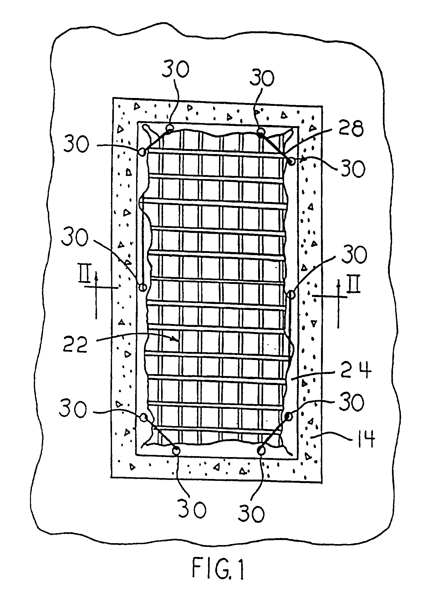
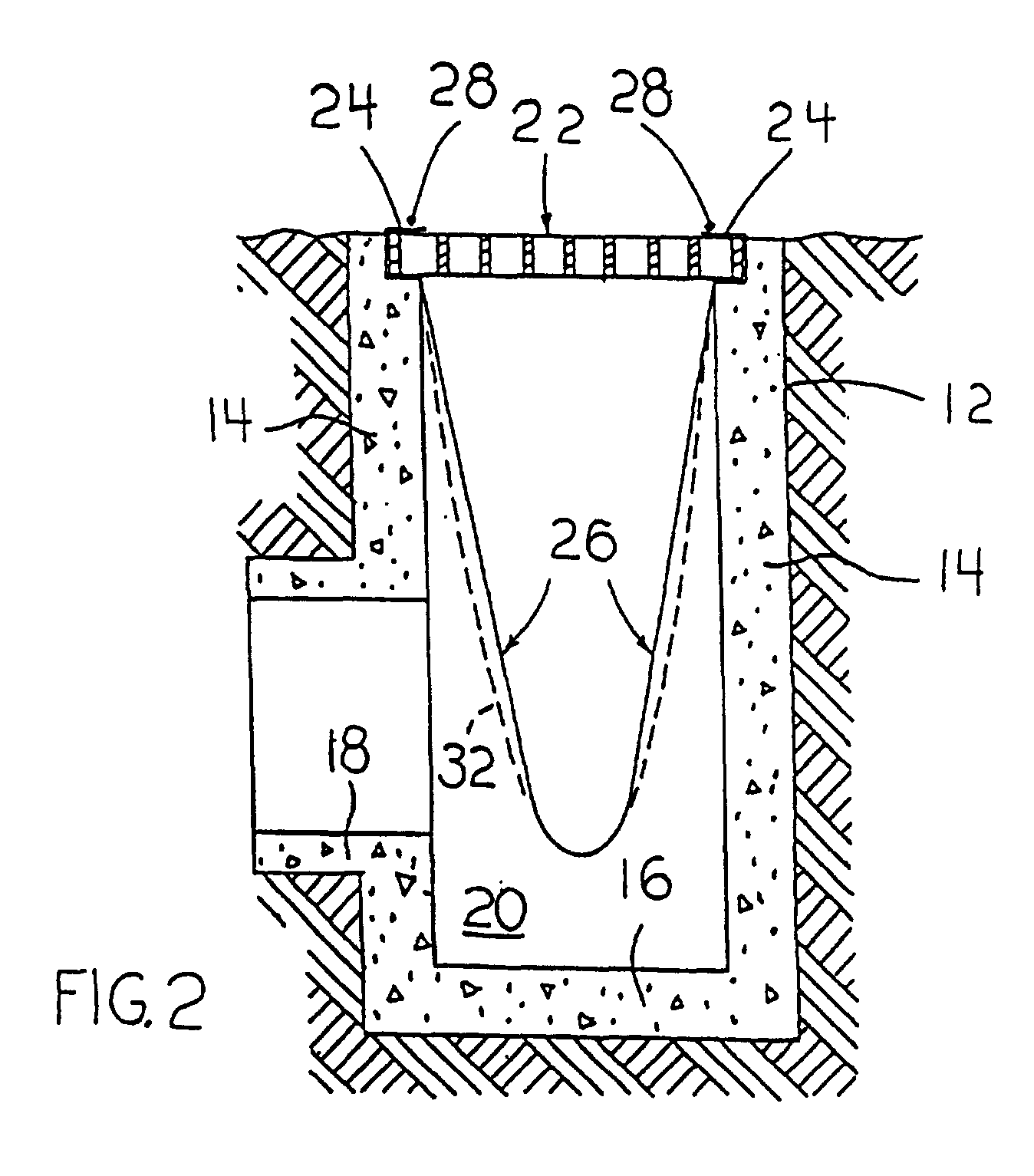
[0009]The concrete catch basin 12 has an inlet grate 22 located at grade level. In ground side walls 14, and floor 16. Floor 16 and side walls 14, define chamber 20. Concrete storm sewer pipe 18 extends away from one of the side walls 14 above floor 16. Rectangular inlet grate 22 closes the catch basin inlet 34. Ground water flows through the grate 22 and into the catch basin chamber 20.

[0010]The catch basin filter includes a filter bag 26 inside the catch basin chamber 20, and also a top opening of the filter bag 24 which enwraps the grate 22. Said filter bag includes four tapered side walls which are joined together to form a filter top opening to receive waste water. Filter bag 26 is preferably made from woven polypropylene fabric. The woven fabric permits water to flow freely through the filter bag 26 while retaining pollutants, including suspended solids, inside of the bag. The side walls form a bottom to retain the pollutants. When filled, the filter bag expands to full shape ...


PUM

PropertyMeasurementUnit
sizeaaaaaaaaaa
weightaaaaaaaaaa
opening sizeaaaaaaaaaa

Abstract

A removable filter for in ground catch basins. The present invention includes a catch basin, a top grate, a filter and an attachment of the filter to the top grate. The filter is held in place both during filtration and filter removal by the filter's attachment to the grate.

Description

BACKGROUND OF THE INVENTION[0001]1. Field of the Invention[0002]This invention relates to a filter for use in a storm sewer catch basin equipped with a top grate. The ground water flows through the grate into the catch basin and into the sewer line. Before the ground water flows into the sewer line it needs to be filtered free of pollutants.[0003]2. Description of the Prior Art[0004]In the past this has been accomplished by placing a filter bag below the grate and inside the catch basin. In U.S. Pat. Nos. 5,575,925 and 5,372,714 the filter bag is held in place by the weight of the grate against the lip of the basin opening. When the bag fills with the weight of filtered solids the bag tends to be pulled past the original position of depth. When the bag is emptied the filter bag is further pulled down into the grate risking the spilling of solids into the basin and the contamination of the sewer line. The slipping of the filter sack into the basin is prevented by the insertion of met...

Claims


Application Information

Patent Timeline
Patent Type & Authority Patents(United States)
IPC IPC(8): E03F5/06B01D29/27E03F1/00
CPCB01D29/27E03F5/0404E03F1/00
Inventor HARRIS, JOHN F.PAGE, ARDLE E.
Owner A PAGE
Features
  • Generate Ideas
  • Intellectual Property
  • Life Sciences
  • Materials
  • Tech Scout
  • Unparalleled Data Quality
  • Higher Quality Content
  • 60% Fewer Hallucinations
Learn More