
Method and apparatus for monitoring a movable barrier over a network

a technology of movable barriers and monitoring systems, applied in the field of movable barriers, can solve the problems of never being notified, people will not remember to check whether the movable barrier is open, and may be left open

Inactive Publication Date: 2006-02-14
THE CHAMBERLAIN GRP INC
View PDF14 Cites 144 Cited by
  • Summary
  • Abstract
  • Description
  • Claims
  • Application Information

AI Technical Summary

Benefits of technology

The patent describes a system that allows a movable barrier to be controlled and monitored through a network. This system includes a network interface that sends the status of the movable barrier to a requesting device or computer. The technical effect of this invention is that it provides a convenient and efficient way to manage and monitor movable barriers remotely, which can save time and reduce costs.

Problems solved by technology

In many instances, generally due to human error, a movable barrier may be left open when the user had intended that it be closed.
Typically, however, a person will not remember to check whether the movable barrier has been left open or will remember at an inconvenient time.
These systems however, require the user to be in the same proximity as the indicator otherwise the user will never be notified of the status of the movable barrier.

Method used


Image

  • Method and apparatus for monitoring a movable barrier over a network
  • Method and apparatus for monitoring a movable barrier over a network
  • Method and apparatus for monitoring a movable barrier over a network

Examples


Embodiment Construction

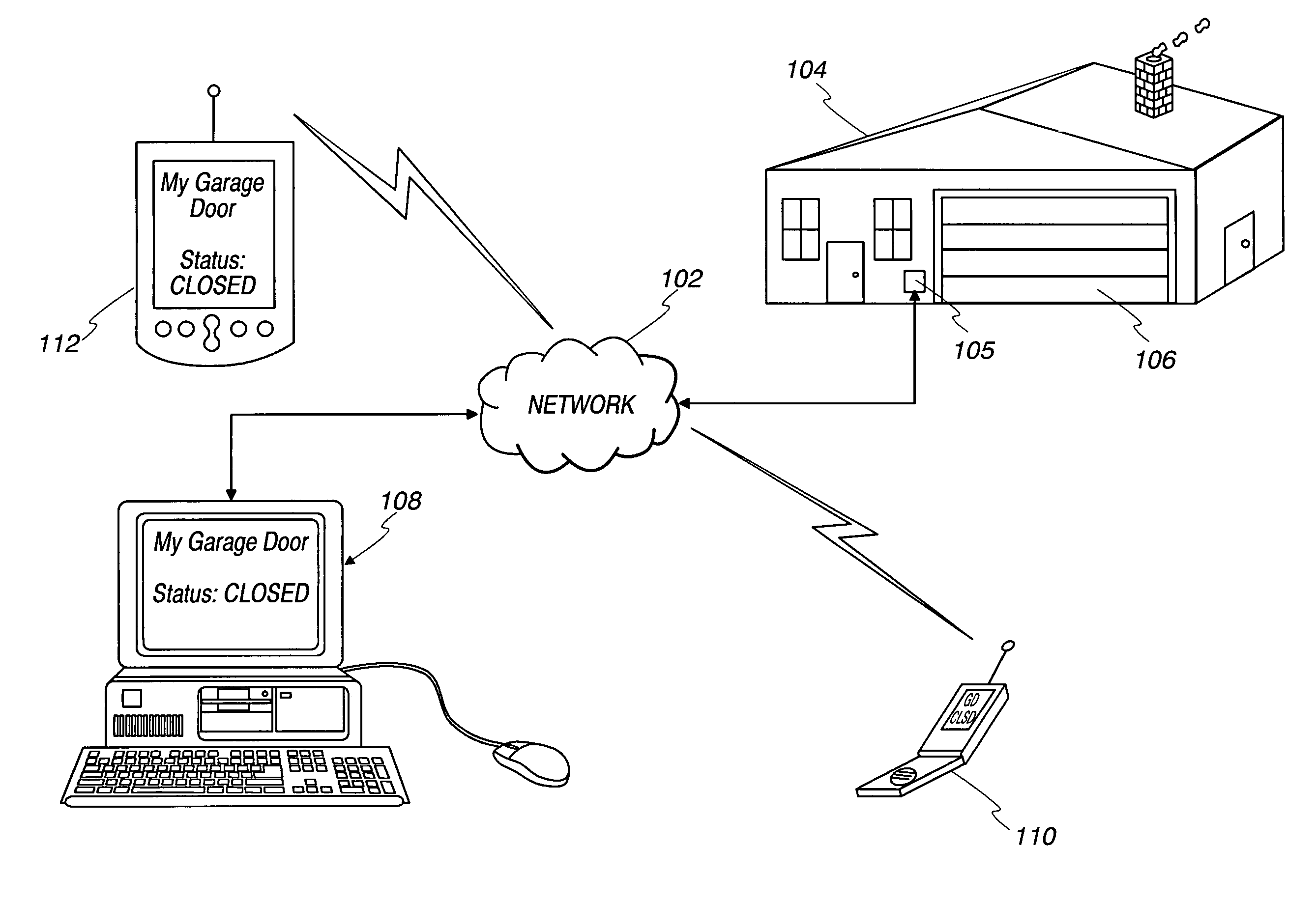
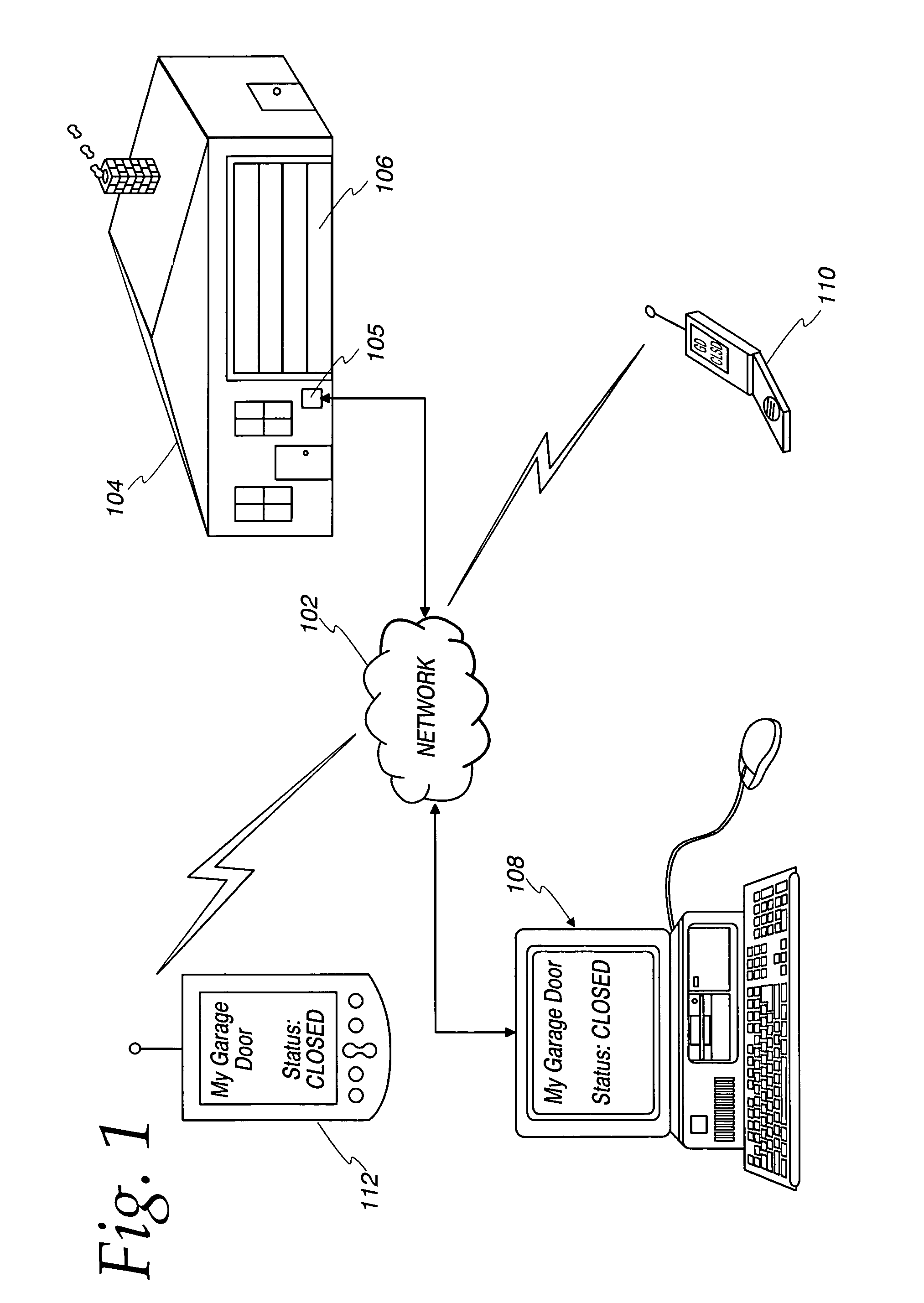
[0015]FIG. 1 is a functional diagram representing a movable barrier 106 and a barrier status monitor or sensor 105 which is connected to a digital network 102 which may, for example, be the well known Internet. Access to the barrier status may be obtained from any device which can communicate over network 102 such as personal computer 108 and properly equipped PDAs 112 and cellular telephone 110. As discussed in more detail below, the network 102 may also be used to send control commands to a movable barrier operator to cause the barrier to be moved on command.

[0016]The movable barrier 106 shown in FIG. 1 is a garage door, however, the movable barrier 106 could be any movable barrier 106, e.g., but not limited to, a gate, a door, a garage door, and a window.

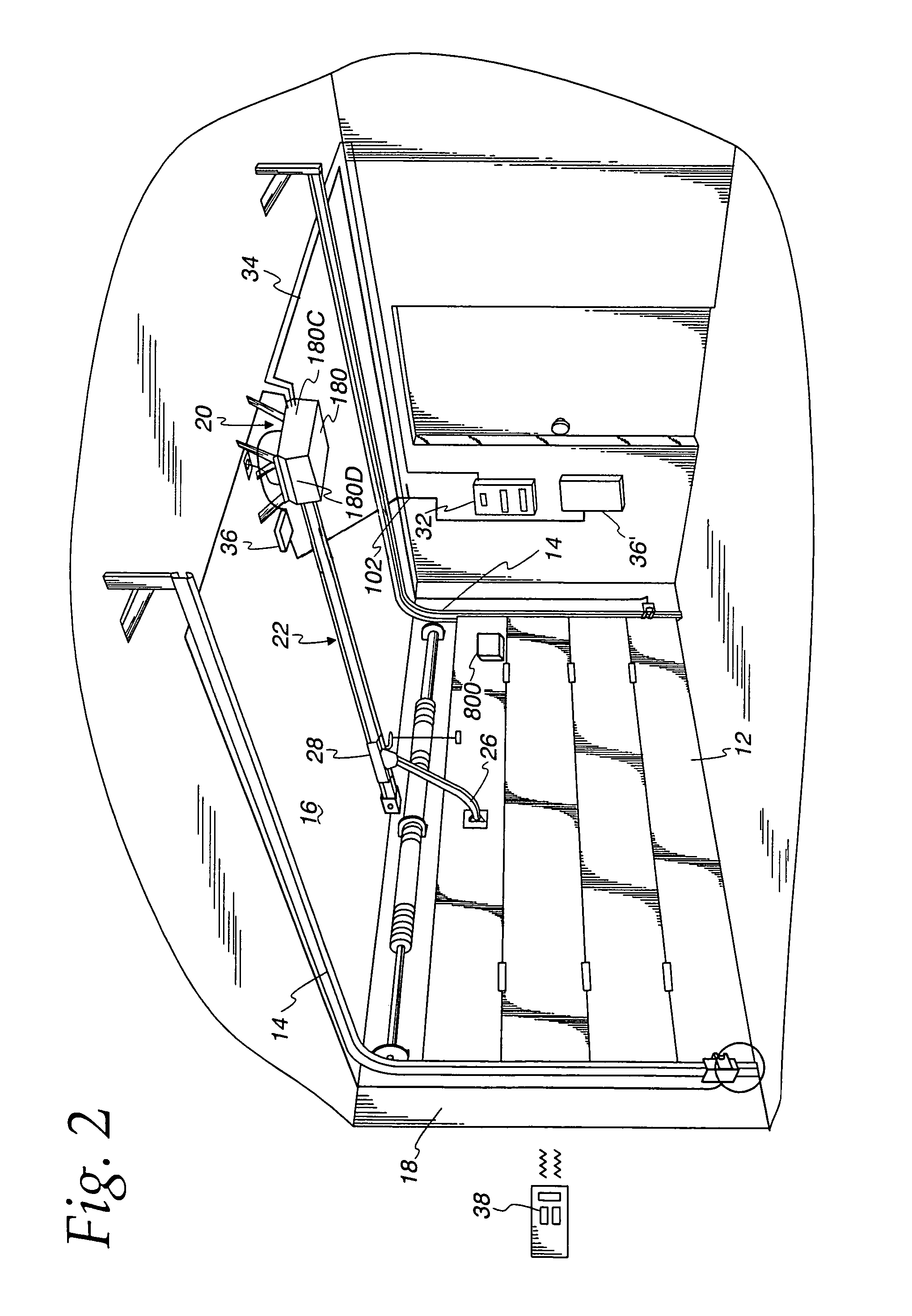
[0017]FIG. 2 illustrates a movable barrier operator for automatically opening and closing a barrier, which operator is connected to a network 102. Shown is a garage door 12, guide rails 14, a ceiling 16, a wall 18, a power drive ...


PUM


Abstract

An apparatus comprising a movable barrier operator for controlling the movable barrier; and a network interface electronically connected to the movable barrier operator for connecting the movable barrier to a network; wherein the network board sends a status of the movable barrier over the network to a requesting device.

Description

RELATED APPLICATIONS[0001]This application is a continuation-in-part of U.S. application Ser. No. 10 / 424,404 filed Apr. 28, 2003.FIELD OF THE INVENTION[0002]The present invention relates generally to movable barriers. More specifically, but without limitation thereto, the present invention relates a monitoring system for a movable barriers.BACKGROUND OF THE INVENTION[0003]Movable barriers, e.g., garage doors, have typically been opened and closed manually by a user. More recently, moveable barriers have been connected to movable barrier operators, e.g., garage door operators. This allows the movable barrier to be opened and closed through the activation of the movable barrier operator. In many instances, generally due to human error, a movable barrier may be left open when the user had intended that it be closed. In order to check the status of the movable barrier the user would go look at the movable barrier to see if it was open or closed. Typically, however, a person will not rem...

Claims


Application Information

Patent Timeline
Patent Type & Authority Patents(United States)
IPC IPC(8): G08B26/00E05F15/16E05F15/20E05F15/60G07C3/00G07C9/00G07F7/00G08B25/08
CPCG07C3/00E05F15/77G07F7/00G08B25/085E05Y2900/106G07C9/00309G07C2009/00928E05F15/668G07C2209/62G08C17/02G08C19/00H04Q9/02
Inventor GREGORI, ERIC M.PETERSON, ERIC
Owner THE CHAMBERLAIN GRP INC
Learn More