Fiber splice device

a fiber splicing and optical fiber technology, applied in the field of fiber splicing devices, can solve the problems of difficult fusion splicing in these types of locations and requiring battery power

Inactive Publication Date: 2006-02-21
3M INNOVATIVE PROPERTIES CO
View PDF24 Cites 25 Cited by
  • Summary
  • Abstract
  • Description
  • Claims
  • Application Information

AI Technical Summary

Problems solved by technology

However, as fiber optics are being deployed deeper into the metro and access areas of the network, splicing in these areas of the network are often performed in the air, in cramped closets, and in difficult-to-maneuver locations.
Fusion splicing in these types of locations is difficult, and often there is no power available for fusion splicing machine, thus requiring battery power.
Also, if many locations are scheduled in a given day, many different installation crews will require fusion splicing machines, resulting in a capital investment for the installation company.

Method used


Image

  • Fiber splice device
  • Fiber splice device
  • Fiber splice device

Examples


first embodiment

[0039]In accordance with exemplary embodiments, in the closed position, stress is induced in the hinge areas on both the locking mechanism and the fiber clamping plate, which forces the respective plates towards an open portion. The structure of the splice device of the present invention is designed to counteract these forces, one opposing the other, to maintain closure of the splice device through the use of a self-locking mechanism. For example, FIGS. 6A and 6B illustrate a self-locking mechanism, where a taper 26A is formed on the tip of the fiber clamping plate 22. This design creates a ramped recess at or near the intersection between the locking plate 24 and the fiber clamping plate 22. In an alternative embodiment, FIGS. 6C and 6D show a raised structure 26B, such as a bump or ridge, that is formed (e.g., by embossing, stamping, coining, or the like) on the surface of the fiber clamping plate 22 at or near the intersection between the locking plate 24 and the fiber clamping p...

second embodiment

[0042]FIG. 8 shows different exemplary fibers 52, 53, such as 250 micrometer diameter buffered fibers, in a second embodiment end port designed for receiving 250-micrometer diameter buffered fibers.

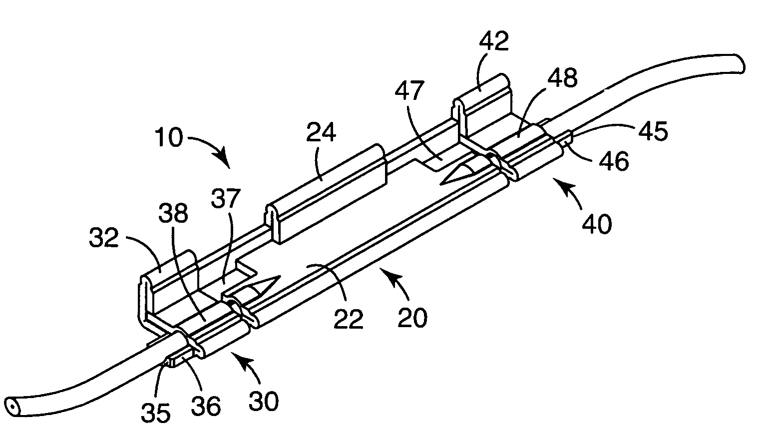
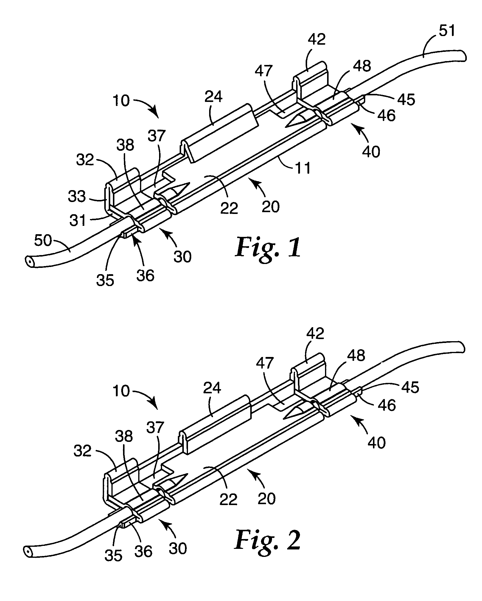
[0043]According to a further alternative embodiment, strain relief can also be accomplished using a modified design and procedure. For example, as shown in FIGS. 9A and 9B, the end port sections 30, 40 can have “open” and “closed” positions, similar to the open and closed positions of the fiber splicing section 20. In the open position, e.g., as shown in FIG. 9A, the fiber 50, 51 (here, an exemplary 900 micrometer outer diameter buffered silica fiber) can be inserted in end ports 35, 45. After the splice is actuated in the fiber splicing section 20, the end port sections 30, 40 can be moved into a closed position by actuating the end port locking plates 32, 42, in a manner similar to that described above. In addition, self-locking mechanisms, such as those described above, can also be emp...


PUM


Abstract

A fiber splice device includes a body comprising a ductile material. First and second end port sections located on opposite ends of the body are provided and are adapted to receive first and second optical fibers, respectively. The splice device further includes a fiber splicing section, adapted to house a fiber splice, located on the body between the end port sections. The fiber splicing section includes a fiber splice actuation section having a self-locking mechanism integral with the body. The splice device can be used in a variety of locations, such as in the access and metro areas of the fiber optic network, and it is not damaged easily.

Description

BACKGROUND OF THE INVENTION[0001]1. Field of the Invention[0002]The present invention is directed to a device for splicing optical fibers. In particular, the present invention is directed to a one-piece fiber splicing device having a self-locking mechanism.[0003]2. Related Art[0004]Mechanical devices for connecting and / or splicing optical fibers for the telecommunications industry are known. For example, conventional devices are described in U.S. Pat. Nos. 4,824,197; 5,102,212; 5,138,681; 5,159,653; 5,337,390; and 5,155,787.[0005]Another preferred conventional splicing method is fusion splicing. In large deployments, many splices are required to be made in many different areas of the city at the same time. However, as fiber optics are being deployed deeper into the metro and access areas of the network, splicing in these areas of the network are often performed in the air, in cramped closets, and in difficult-to-maneuver locations. Fusion splicing in these types of locations is diff...

Claims


Application Information

Patent Timeline
Patent Type & Authority Patents(United States)
IPC IPC(8): G02B6/255G02B6/38
CPCG02B6/3801G02B6/3802G02B6/36G02B6/38
Inventor CARPENTER, JAMES B.ELDER, DALE E.
Owner 3M INNOVATIVE PROPERTIES CO
Why Eureka
Try Eureka