Loadlock apparatus and structure for creating a seal between an elevator drive shaft and the loadlock chamber thereof

a technology of loading chamber and loadlock, which is applied in the direction of lighting and heating apparatus, charge manipulation, furniture, etc., can solve the problems of the most difficult portion of the loadlock chamber b>, and achieve the effect of sealing structur

Inactive Publication Date: 2006-02-21
SAMSUNG ELECTRONICS CO LTD
View PDF6 Cites 5 Cited by
  • Summary
  • Abstract
  • Description
  • Claims
  • Application Information

AI Technical Summary

Benefits of technology

[0010]Therefore, an object of the present invention is to provide sealing structure that is capable of always maintaining a seal between an elevator drive shaft and a loadlock chamber regardless of the position of the elevator shaft.
[0011]Another object of the present invention is to provide sealing structure that is capable of maintaining a uniform contact force between a seal of the structure and an elevator drive shaft, thereby prolonging the useful life of the seal, and the time between servicing the sealing structure.

Problems solved by technology

In particular, the most difficult portion of the loadlock chamber 10 to keep sealed is that portion where the elevator drive shaft 22 extends through the bottom of the loadlock chamber 10.
However, a leak check executed after the sealing structure 30 and the elevator shaft 22 are assembled and are integrated with the loadlock chamber 10 often reveals a leak.

Method used


Image

  • Loadlock apparatus and structure for creating a seal between an elevator drive shaft and the loadlock chamber thereof
  • Loadlock apparatus and structure for creating a seal between an elevator drive shaft and the loadlock chamber thereof
  • Loadlock apparatus and structure for creating a seal between an elevator drive shaft and the loadlock chamber thereof

Examples


Embodiment Construction

[0022]Hereinafter, preferred embodiments of the present invention will be described in detail with reference to FIGS. 5–7.

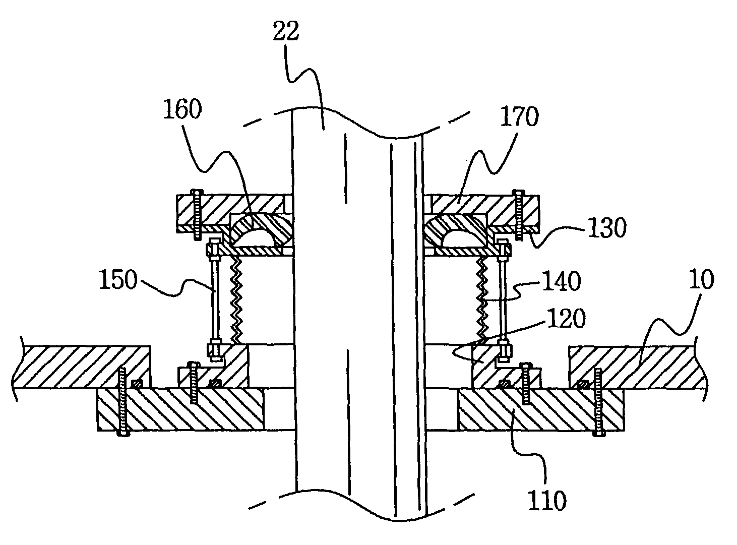
[0023]Referring first to FIG. 5, reference numeral 10 designates a loadlock chamber and reference numeral 22 designates an elevator drive shaft.

[0024]As was previously discussed, the loadlock chamber 10 is generally vacant, and is connected to a process chamber to allow wafers received from the outside to be loaded into the process chamber under the same atmosphere as prevails in the process chamber. Likewise, the loadlock chamber receives processed wafers from the process chamber and allows the processed wafers to be transferred to the outside without exposing the interior of the process chamber to the outside atmosphere. In other words, the loadlock chamber 10 forms an airtight space that connects the outside and the process chamber.

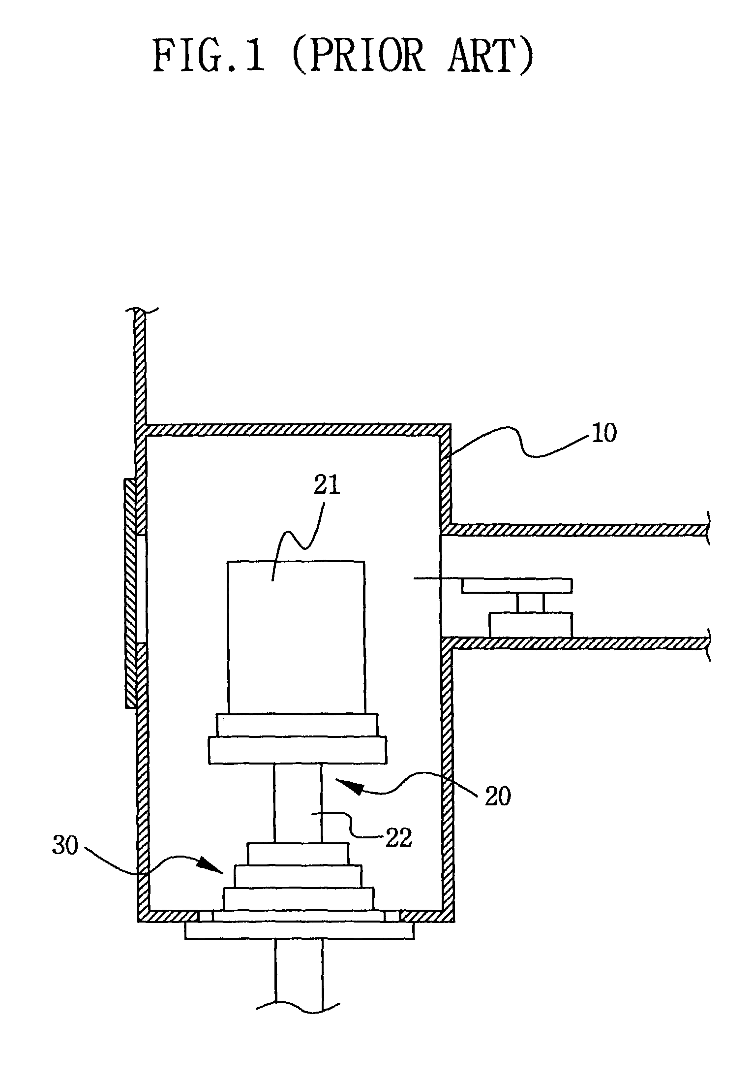
[0025]An elevator is used to facilitate the transfer of a batch of wafers in the manner described above. The elevator includes an ...


PUM


Abstract

Sealing structure for use in creating a seal between an elevator drive shaft and a loadlock chamber includes a base fastened over a hole in the bottom wall of the loadlock chamber, a fixed member fastened to an upper part of the base, a seal housing spaced above the fixed member, a cap in the form of a flexible bellows having a first end adhered to an upper surface of the fixed member and a second end adhered to a lower surface of the seal housing, one or more support shafts having upper and lower ends pivotally connected to the seal housing and the fixed member outside the cap, a seal seated in the seal housing and having an inner circumferential surface contacting the outer circumferential surface of the elevator drive shaft, and a seal cover fixed to an upper part of the seal housing. According to the present invention, uniform pressure is maintained between the shaft and the seal during assembly and operation of the apparatus. Thus, a seal is always maintained between the elevator drive shaft and the bottom wall of the loadlock chamber.

Description

BACKGROUND OF THE INVENTION[0001]1. Field of the Invention[0002]The present invention relates to a loadlock apparatus having a loadlock chamber and an elevator extending into the loadlock chamber. More particularly, the present invention relates to sealing structure that creates a seal between a drive shaft of the elevator and the loadlock chamber into which the drive shaft extends.[0003]2. Description of the Related Art[0004]In general, in the fabricating of a semiconductor device, a wafer is passed through a loadlock chamber before being introduced into a process chamber in which the wafer is processed in a vacuum. Such a loadlock chamber receives the non-processed wafer from the outside under atmospheric pressure. The wafer is then loaded from the loadlock camber into the process chamber under the same vacuum atmosphere as the process chamber. The processed wafer is returned to the loadlock chamber and is then transferred from there for subsequent processing.[0005]FIG. 1 shows su...

Claims


Application Information

Patent Timeline
Patent Type & Authority Patents(United States)
IPC IPC(8): B65G49/07H01L21/02H01L21/00
CPCH01L21/67126Y10S414/139H01L21/02
Inventor KIM, HO
Owner SAMSUNG ELECTRONICS CO LTD
Why Eureka
Try Eureka