

Burner with internal separator
a burner and separator technology, applied in the field of burners, can solve problems such as inability to operate, and achieve the effects of improving the efficiency of combustion and reducing the cost of production
Inactive Publication Date: 2006-02-21
SABAF SPA
View PDF11 Cites 21 Cited by
- Summary
- Abstract
- Description
- Claims
- Application Information
AI Technical Summary
Problems solved by technology
Notwithstanding the advantage of being made up of just two die-cast pieces, this burner presents, however, certain drawbacks; in particular, using just two die-cast pieces it is not possible to make, inside the burner, all the ducts necessary for the passage of the primary air and of the gas / primary air mixture.
In fact, in this burner, the ducts that carry the gas / primary air mixture from the mixing chamber to the circumferential crowns are not altogether made in the body of the burner, but are defined by ducts delimited at the top only by planar appendages that join the central cap to the annular burner cap, a solution which is not ideal given the consequent inevitable leakages of mixture and the possibility of undesired displacements of said burner caps.
Method used
View moreImage
Smart ImageViewing Examples

Examples
example
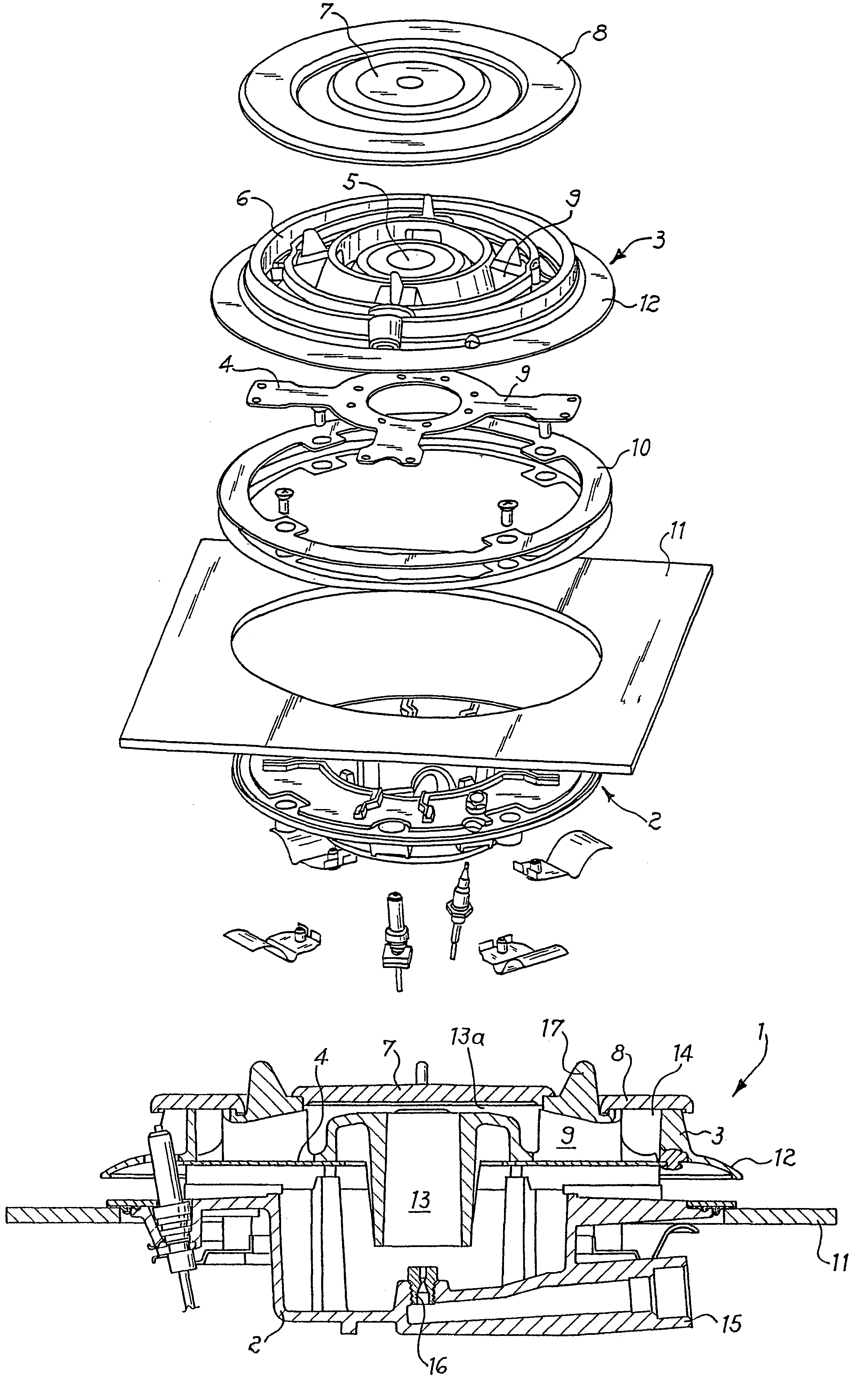
[0037]With reference now to FIG. 7, showing an example of embodiment of the present invention, the burner body 102 and the burner head 103 are made in aluminium alloy (Al—Si and / or Al—Ni) or brass by die-casting and the flat internal element 109 is obtained by drawing a steel, stainless steel, or brass sheet.
[0038]Furthermore, the holes 201 of the central flame crown are realized on the peripheral wall of the central chamber 105 and they are tilted with respect to the vertical axis Y of the burner at an angle β of between 40 and 70 degrees.
Login to View More PUM
 Abstract
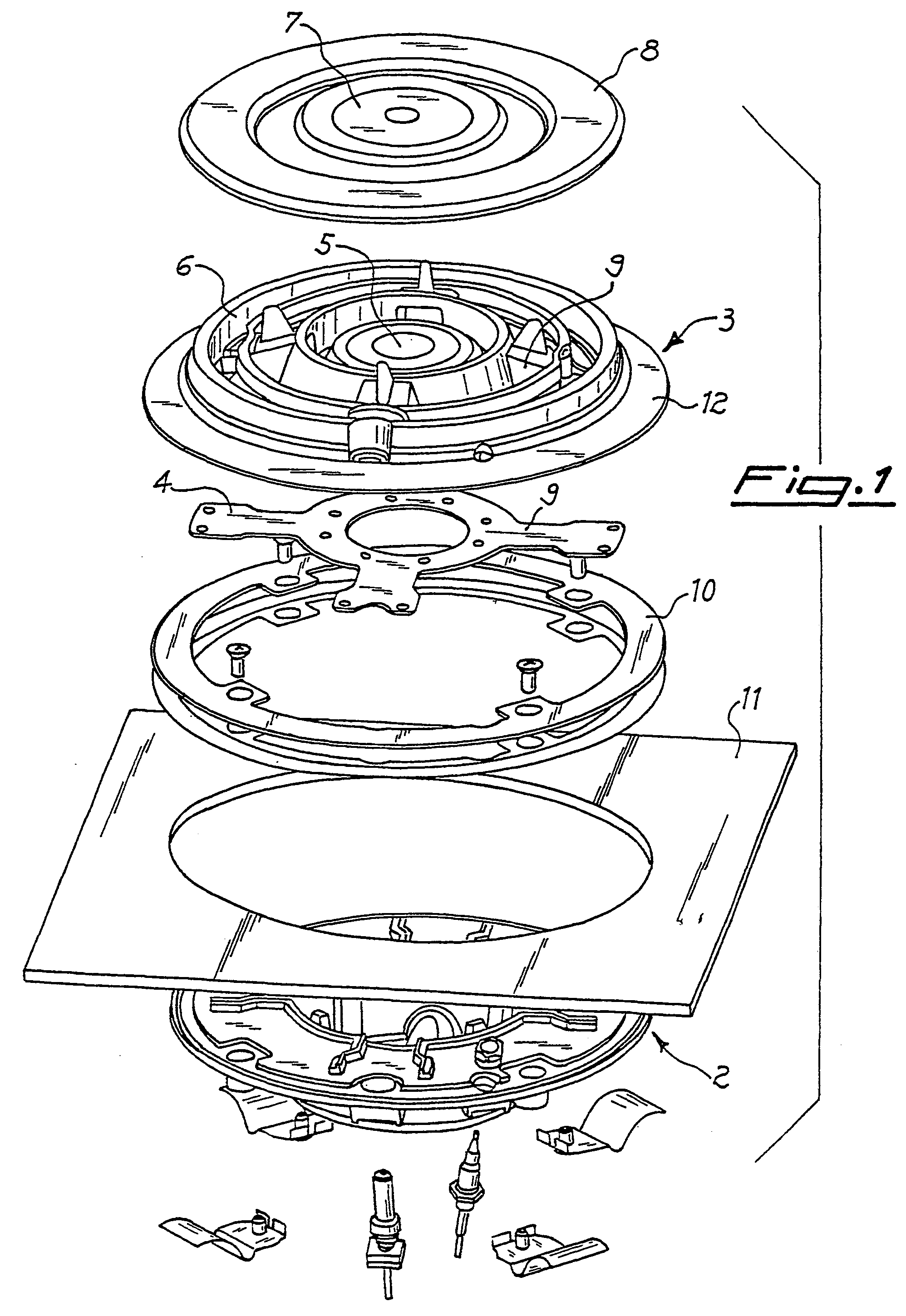
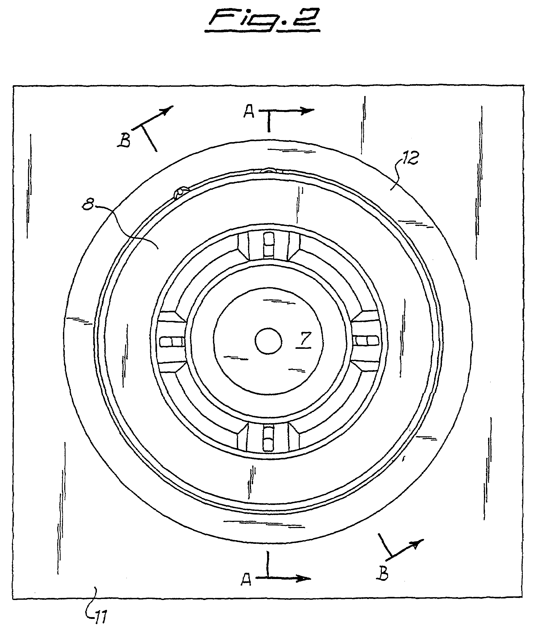
The invention relates to a burner (1) for cookers, suitable for burning gas, comprising at least two gas crowns, of which one central one and at least one circumferential one, a mixing chamber (13) with Venturi effect, ducts for entry of the primary air and radial ducts (9) for feeding the gas / primary air mixture to the said at least one circumferential crown, comprising a body (3), a head (2) and a separation element (4) that breaks up the internal space into ducts for entry of the primary air and ducts for distribution of the gas / primary air mixture.
Description
TECHNICAL FIELD[0001]The present invention relates to a burner for cookers equipped with two or more gas crowns, more in particular a burner suitable for use in built-in cooking surfaces.BACKGROUND ART[0002]There are known burners for cookers provided with two or three gas crowns, in particular burners with three crowns, a central one and two outer ones, one facing the inside and one facing the outside of the burner.[0003]This type of burner enables uniform heating of the pans that are set on them irrespective of the shape and size of the pans.[0004]In the European patent application EP 0 797 048 in the name of the present applicant, a burner with three gas crowns is described which is provided with a horizontal Venturi made in a chamber formed between a base of the burner and an upper portion comprising the central gas crown. The chamber of the Venturi communicates with an upper chamber defined by the bottom of the area of central crown and by the central burner cap. This burner is...
Claims
Login to View More Application Information
Patent Timeline
 Patent Type & AuthorityPatents(United States)
IPC IPC(8): F23D14/62F23D14/06F23D14/64F24C3/02F24C3/08
CPCF23D14/065F24C3/085F23D2212/20Y02B40/166F23D2900/14062F23D2213/00Y02B40/00F23D14/06
InventorBETTINZOLI, ANGELO
OwnerSABAF SPA