
Method and apparatus for releasably attaching a polishing pad to a chemical-mechanical planarization machine

a technology of chemical-mechanical planarization machine and polishing pad, which is applied in the direction of work holders, grain treatment, manufacturing tools, etc., can solve the problems of affecting the quality of polishing,

Inactive Publication Date: 2006-02-21
MICRON TECH INC
View PDF23 Cites 35 Cited by
  • Summary
  • Abstract
  • Description
  • Claims
  • Application Information

AI Technical Summary

Benefits of technology

The present invention is about a way to attach a polishing pad to a machine that removes unevenness from a semiconductor substrate. The machine has a platen with vacuum apertures that hold the pad tightly against the platen when the vacuum is applied. The pad can be made of a non-porous or porous material, and it can be supported by a pad support or a jig to condition it. The platen can move and has a lip to keep the pad in place. The invention also includes a base that advances the pad across the platen when the vacuum is applied. This allows for longer use of the pad and easier replacement of the worn-out portion of the pad.

Problems solved by technology

Focusing photo-patterns of such small tolerances, however, is difficult when the planarized surface of the wafer is not uniformly planar.
One problem with conventional CMP processing techniques is that the planarized surface of the wafer may not be sufficiently uniform due to nonuniformities that may develop in the planarizing surface of the polishing pad during planarization.
One drawback with this approach is that the planarizing surface of the polishing pad typically wears out during normal use and the polishing pad must therefore be replaced.
It may be difficult and time consuming to remove the polishing pad and the high-strength adhesive from the platen, rendering the CMP machine inoperable for extended periods of time.
One problem with this approach is that the tension in the sheet may not be sufficient to keep it flat against the platen.

Method used


Image

  • Method and apparatus for releasably attaching a polishing pad to a chemical-mechanical planarization machine
  • Method and apparatus for releasably attaching a polishing pad to a chemical-mechanical planarization machine
  • Method and apparatus for releasably attaching a polishing pad to a chemical-mechanical planarization machine

Examples


Embodiment Construction

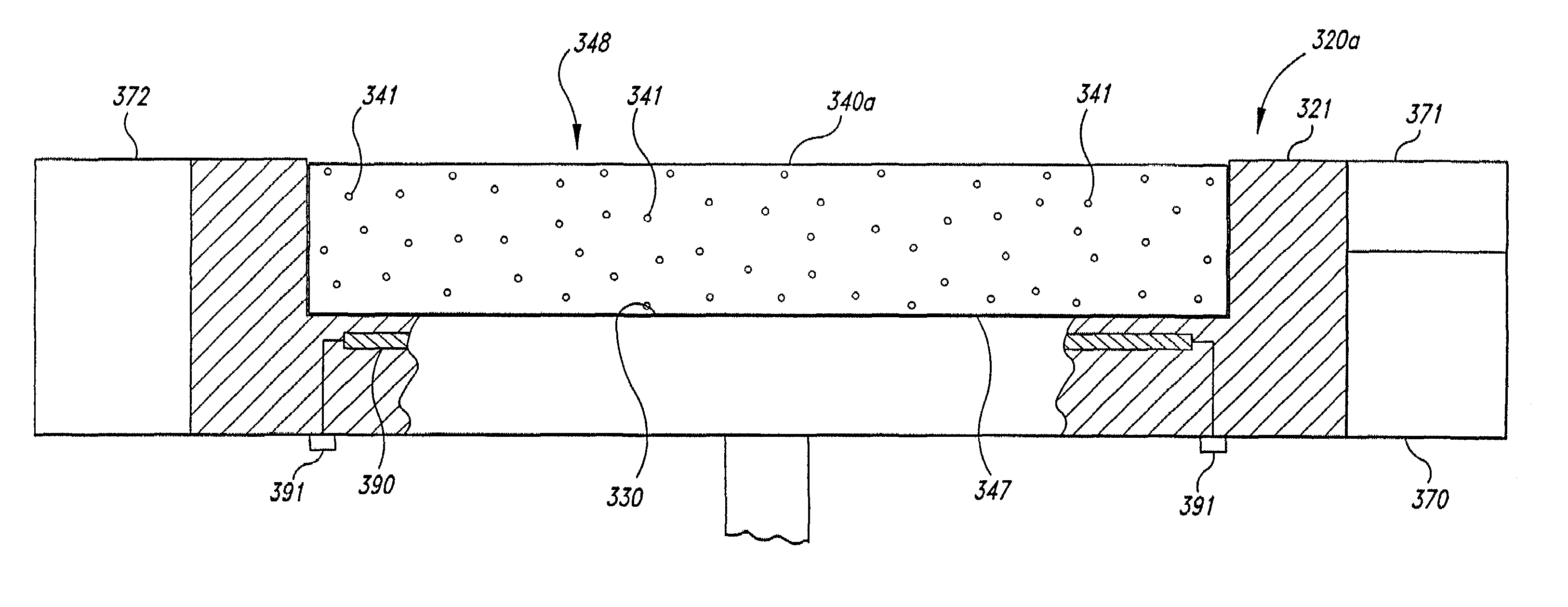
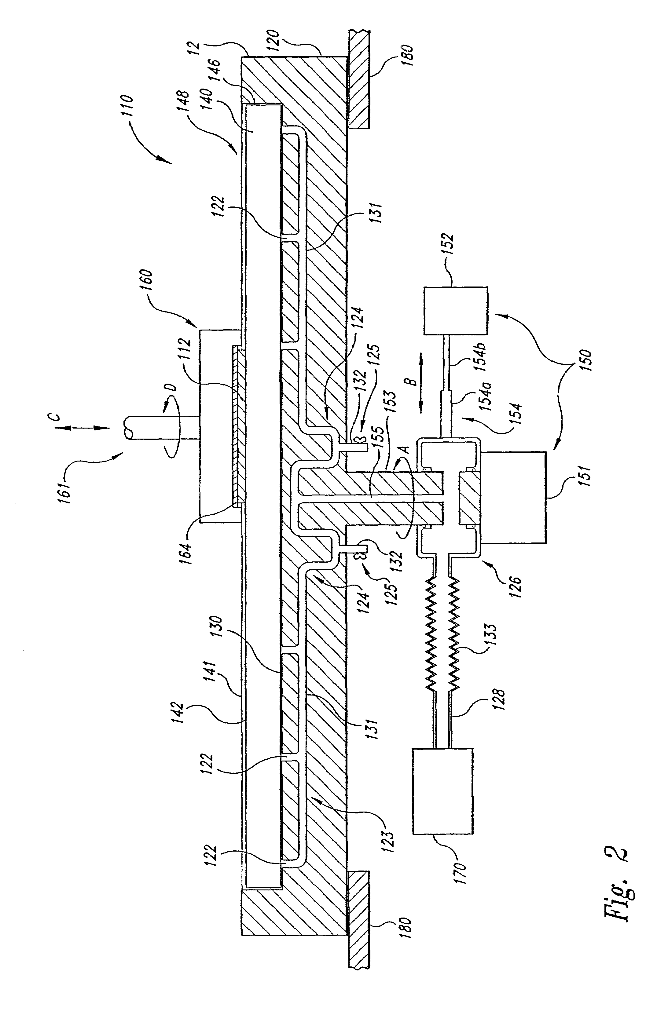
[0022]The present invention is directed toward methods and devices for attaching a polishing pad to a platen of a chemical-mechanical planarization machine. The device may include a vacuum system that releasably attaches the polishing pad to the platen such that the polishing pad may be easily removed and / or replaced, or may be incrementally advanced over the platen. Many specific details of certain embodiments of the invention are set forth in the following description and in FIGS. 2–7 to provide a thorough understanding of such embodiments. One skilled in the art, however, will understand that the present invention may have additional embodiments and that they may be practiced without several of the details described in the following description.

[0023]FIG. 2 illustrates a CMP apparatus 110 having a platen 120 and a planarizing medium 148. In the embodiment shown in FIG. 2, the planarizing medium 148 includes polishing pad 140 releasably attached to the platen 120, and in other emb...


PUM

PropertyMeasurementUnit
vacuum pressureaaaaaaaaaa
electromagnetic attractive forceaaaaaaaaaa
conductiveaaaaaaaaaa

Abstract

A method and apparatus for releasably attaching a planarizing medium, such as a polishing pad, to the platen of a chemical-mechanical planarization machine. In one embodiment, the apparatus can include several apertures in the upper surface of the platen that are coupled to a vacuum source. When a vacuum is drawn through the apertures in the platen, the polishing pad is drawn tightly against the platen and may therefore be less likely to wrinkle when a semiconductor substrate is engaged with the polishing pad during planarization. When the vacuum is released, the polishing pad can be easily separated from the platen. The apparatus can further include a liquid trap to separate liquid from the fluid drawn by the vacuum source through the apertures, and can also include a releasable stop to prevent the polishing pad from separating from the platen should the vacuum source be deactivated while the platen is in motion. In another embodiment, a signal can be applied to the platen to draw the polishing pad toward the platen via electrostatic or electromagnetic forces. In still another embodiment, the polishing pad can be attached to a pad support and conditioned on a separate jig.

Description

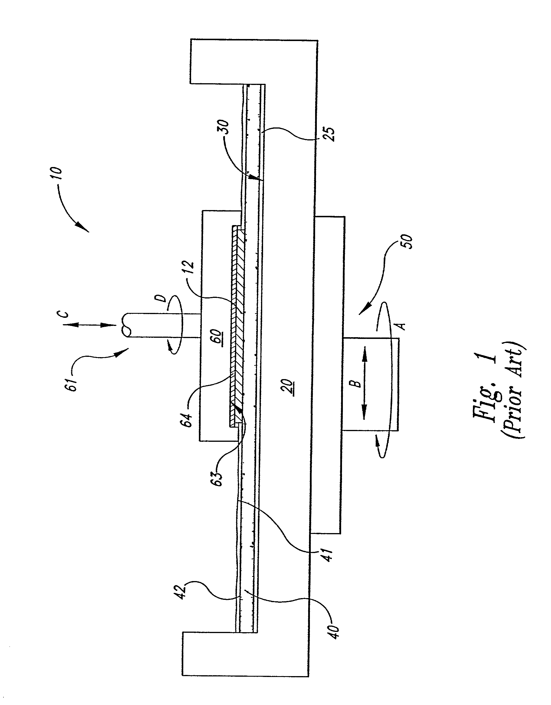
CROSS-REFERENCE TO RELATED APPLICATIONS[0001]This application is a divisional of U.S. patent application Ser. No. 09 / 539,854, filed Mar. 31, 2000 now U.S. Pat. No. 6,482,077, which is a divisional on U.S. patent application Ser. No. 09 / 181,578, filed Oct. 28, 1998 now U.S. Pat. No. 6,602,380.TECHNICAL FIELD[0002]The present invention relates to methods and devices for releasably attaching polishing pads to the platens of chemical-mechanical planarization machines.BACKGROUND OF THE INVENTION[0003]Chemical-mechanical planarization (“CMP”) processes remove material from the surface of a semiconductor wafer in the production of integrated circuits. FIG. 1 schematically illustrates a CMP machine 10 with a platen 20, a wafer carrier 60, a polishing pad 40, and a planarizing liquid 41 on the polishing pad 40. The polishing pad 40 may be a conventional polishing pad made from a continuous phase matrix material (e.g., polyurethane), or it may be a fixed abrasive polishing pad made from abras...

Claims


Application Information

Patent Timeline
Patent Type & Authority Patents(United States)
IPC IPC(8): B24B1/00B24B37/11B24B37/14B24D9/08B25B11/00
CPCB24B37/11B25B11/005B24D9/085B24B37/14
Inventor DOAN, TRUNG TRIMOORE, SCOTT E.
Owner MICRON TECH INC
Learn More