Patient comfort apparatus and system

a patient comfort and apparatus technology, applied in the field of patient comfort systems, can solve the problems of severe curtailing, inconvenient use of inflatable blankets, and inability to easily or readily deploy on persons standing, and achieve the effects of ensuring comfort for patients, effective convective heating, and simple manufacturing, storage and deploymen

Inactive Publication Date: 2006-02-21
3M INNOVATIVE PROPERTIES CO +1
View PDF12 Cites 97 Cited by
  • Summary
  • Abstract
  • Description
  • Claims
  • Application Information

AI Technical Summary

Benefits of technology

[0015]The invention provides pneumatic convective thermal treatment of the feeling of being cold by means of pneumatic convective for use on a patient in a clinical setting. The invention includes a pneumatic convective device, as well as a system and method employing such a device to maintain comfort a patient by warming. The pneumatic convective devices provide effective convective warming that is focused or directed primarily on or to the most thermally sensitive regions of a user. These devices are also simple to manufacture, store, and deploy for use. Finally, because this invention is meant to produce or induce a state of thermal comfort in a patient, without providing hypothermia therapy, airflow exiting the pneumatic convective device of less than 15 CFM (cubic feet per minute) and a temperature of less than 105° F. are preferred.

Problems solved by technology

Because these devices are designed to cover and hang about or over a supine person, they are not easily or readily deployed on persons who are standing, sitting, reclining or moving.
In particular, inflatable blankets are not suitable in a clinical setting in which it is desirable to warm a patient, and also necessary that the patient be able to move about and between various postures.
Further, patient mobility throughout a clinic or a hospital is highly desirable, but would be severely curtailed with use of inflatable blankets.
For example, transporting a patient to an x-ray or MRI location in a wheelchair, would be made problematic with an inflatable blanket.
However, this adaptation has a limited use in that a person using it must remain in a sitting or reclining posture in order for the device to drape over the person's body and retain warmed air and heat about the person.
Such devices are not designed to accommodate movement or changes in the person's posture or to allow easy access to patient anatomy.
These devices are even less adaptable than blanket devices for non-supine uses.
The cold discomfort can cause a one hour wait to seem like 2 hours to the patient.
People tend to vasoconstrict when frightened, and vasoconstriction can lead to reduced peripheral temperature and increased blood pressure, and can make IV access much more difficult.
Finally, there is evidence that feeling cold increases the perception of pain.
An inflatable blanket or cover could be deployed for this purpose, but would be very impractical because the patient would be required to remain supine or maintain a prone or sitting position.
Its normally closed configuration and complicated pneumatics make this device inconvenient and impractical to use for patient comfort in a clinical environment.
This device's structure and operation make it also unsuitable for use in maintaining patient comfort in a clinical environment.

Method used


Image

  • Patient comfort apparatus and system
  • Patient comfort apparatus and system
  • Patient comfort apparatus and system

Examples


Embodiment Construction

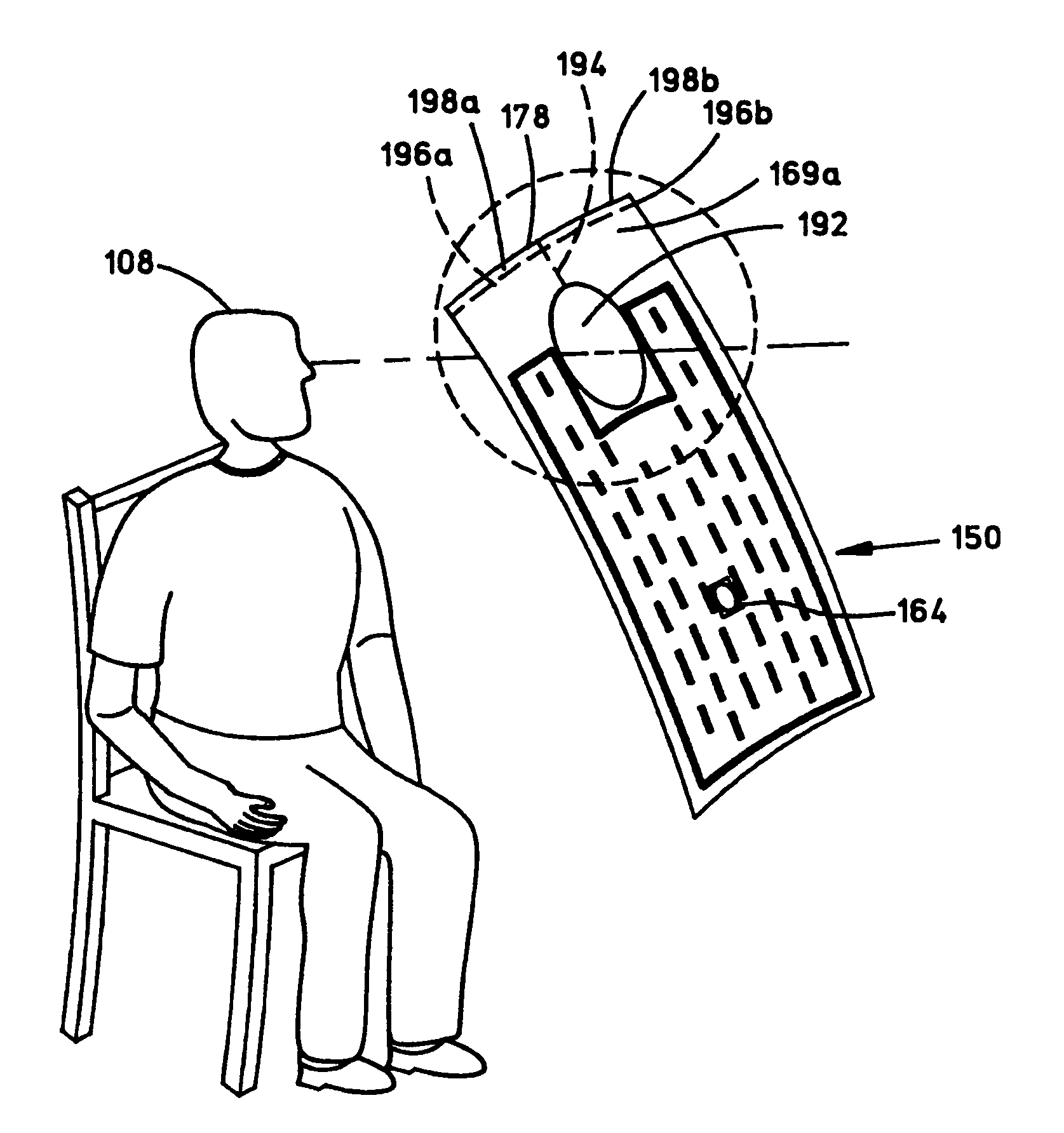
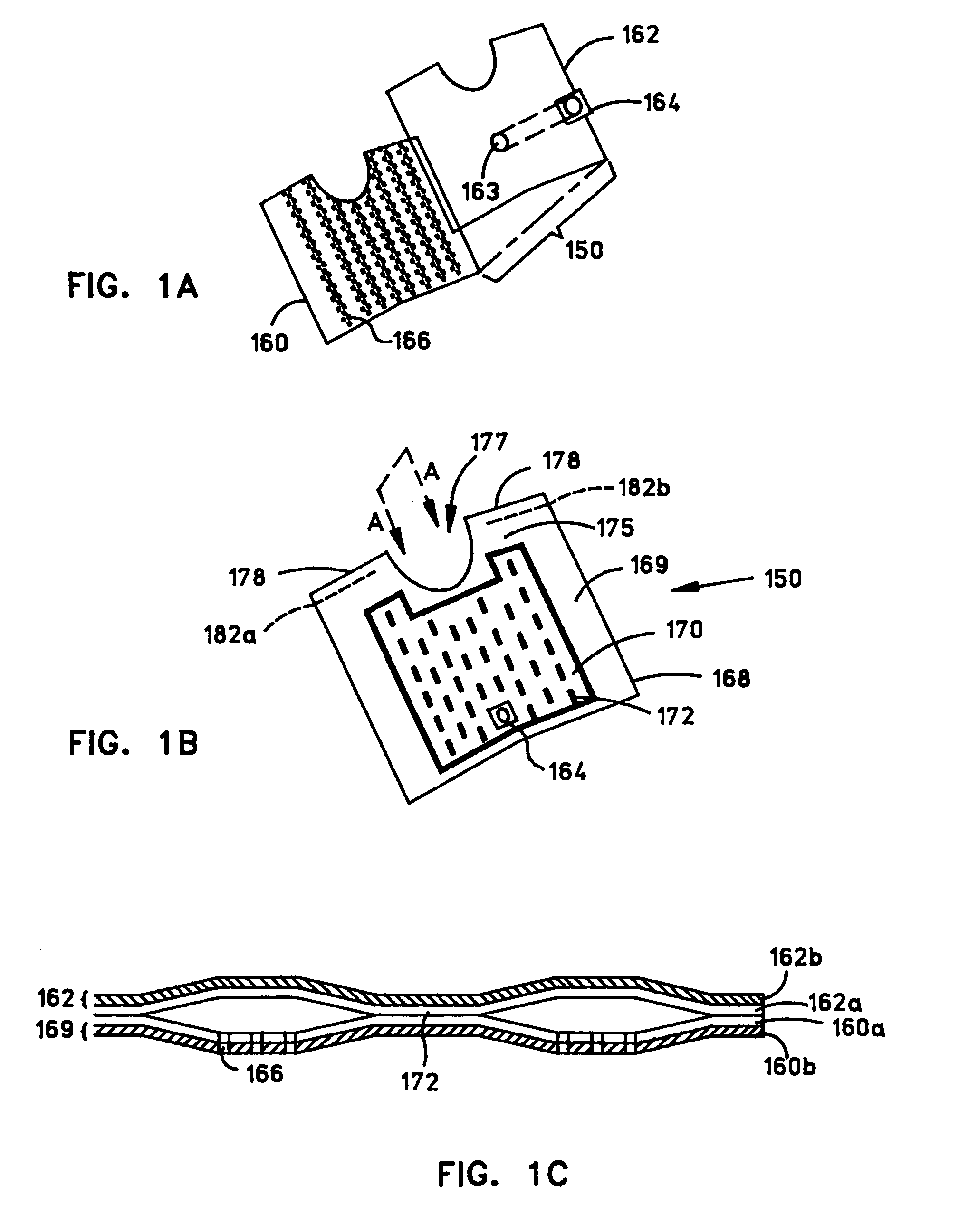
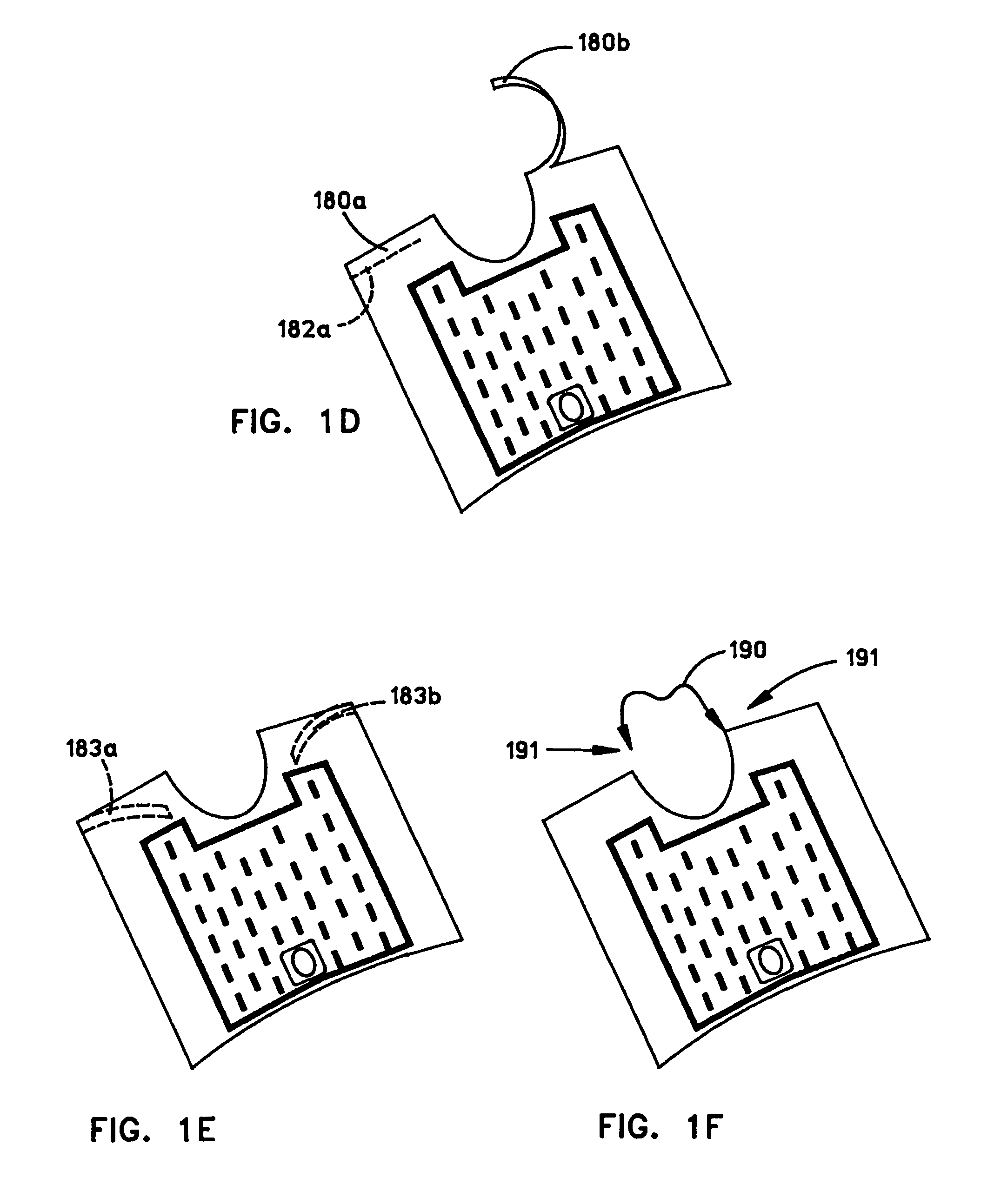
[0018]The invention is embodied as a pneumatic convective device receivable on a human or animal body in a clinical setting which receives a stream of pressurized, thermally conditioned air, distributes the pressurized air within a pneumatic structure, and emits the air through one or more surfaces for convective transfer of heat between the thermally conditioned air and the body. Various specific embodiments of the invention are illustrated and discussed according to an example in which a human body is warmed by focusing or concentrating convective warming on the body core in order to permit patient movement and to enhance clinical convenience, although this is not intended to suggest that the invention may not be used for cooling, which, indeed, it may. The pneumatic convective device may be deployed for use with humans, animals, patients, clinicians, practitioners, observers, and so on.

[0019]Further, use of the term “convective” to denote the transfer of heat to a body refers to ...


PUM

PropertyMeasurementUnit
temperatureaaaaaaaaaa
angleaaaaaaaaaa

Abstract

Apparatus and a system for thermally comforting a patient include pneumatic, convective device providing thermal treatment for persons or animals. The pneumatic convective device is adapted to fit around a person's neck and provides convective warming focused or directed primarily on the thorax or body core. The pneumatic convective device includes an inlet, a region in distribution with the inlet for distributing a stream of pressurized, thermally treated air, and a permeable member for emitting pressurized, thermally treated air from the distribution region.

Description

CROSS REFERENCE TO RELATED APPLICATIONS[0001]This application claims the benefit of U.S. Provisional No 60 / 371,314 filed Apr. 10, 2002.[0002]This application contains subject matter related to that of U.S. patent application Ser. No. 10 / 411,431, for “FORCED AIR WARMING UNIT” and PCT Patent Application Serial No. PCT / US03 / 11128, for “PATIENT COMFORT APPARATUS AND SYSTEM”, filed concurrently with this application, and to that of U.S. Design patent application Ser. No. 20 / 179,545, for “FORCED AIR WARMING UNIT”, now U.S. Pat. No. D485,338.BACKGROUND OF THE INVENTION[0003]1. Field of the Invention[0004]The invention is directed to a patient comfort system that includes pneumatic convective devices receivable on a human or animal body which receive a stream of pressurized, thermally conditioned air, distribute the pressurized air within a pneumatic structure, and emit the air through one or more surfaces for convective transfer of heat between the thermally conditioned air and the body. I...

Claims


Application Information

Patent Timeline
Patent Type & Authority Patents(United States)
IPC IPC(8): A61F7/00A41D13/00A41D13/12A41D27/22A61F7/02
CPCA61F7/00A61F7/02F16L31/00F16L37/098A61F7/0085A41D13/0025A41D2400/32A61F2007/0018A61F2007/006A61F2007/0091A61F2007/0094A61F2007/0234A61F2310/0097A41D2400/14A61F7/0097
Inventor AUGUSTINE, SCOTT D.ANDERSON, THOMAS PETERARNOLD, RANDALL C.
Owner 3M INNOVATIVE PROPERTIES CO
Why Eureka
Try Eureka