Video contrast enhancement through partial histogram equalization

a video contrast and partial histogram technology, applied in image enhancement, television systems, instruments, etc., can solve the problem that the best place to perform large intensity shifts on large numbers of pixels is typically the frame-adaptive video contrast enhancement, and achieve good contrast enhancement

Inactive Publication Date: 2006-02-21
RAKUTEN GRP INC
View PDF10 Cites 110 Cited by
  • Summary
  • Abstract
  • Description
  • Claims
  • Application Information

AI Technical Summary

Problems solved by technology

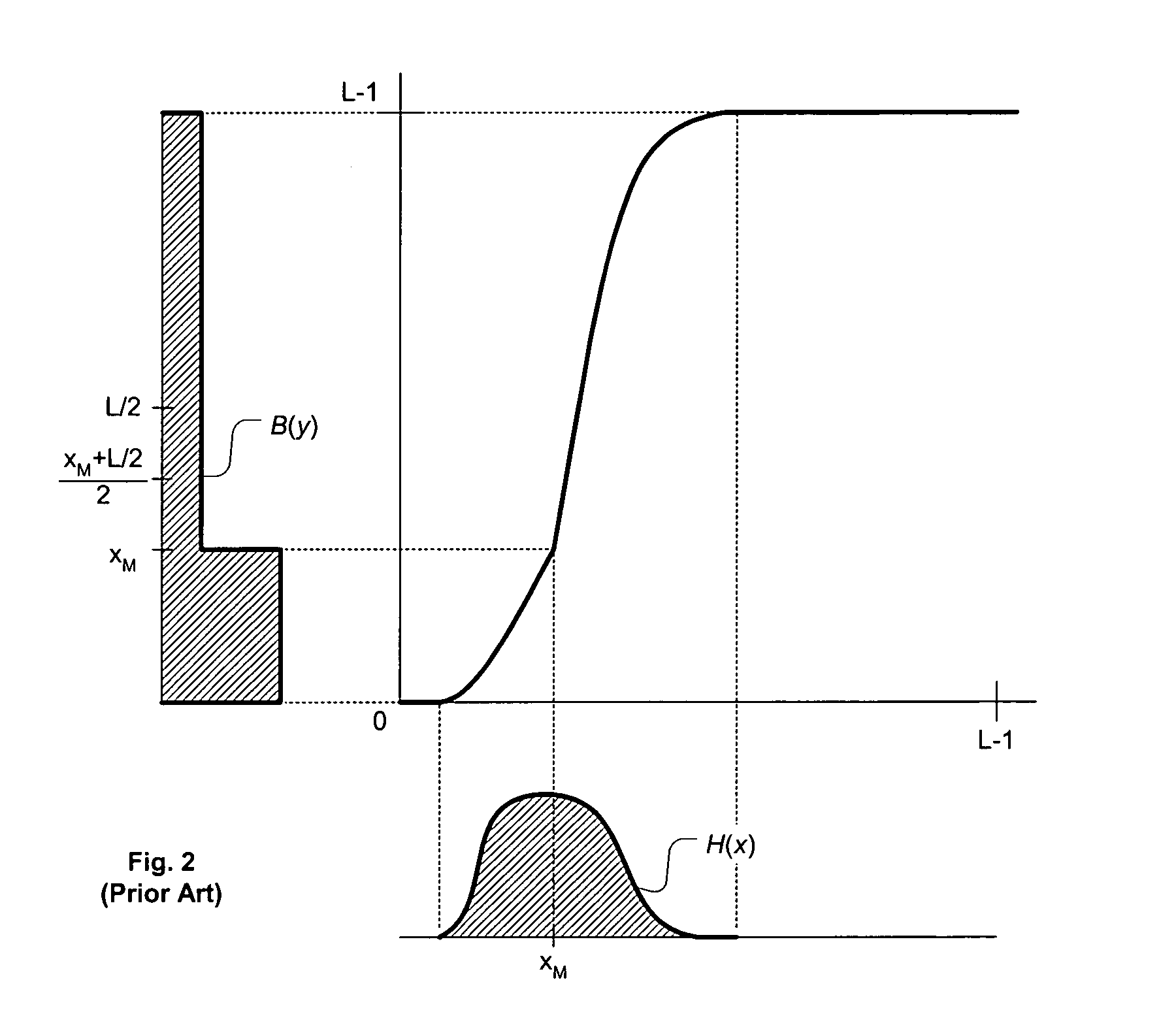
If this assumption is not correct, a scene-constant brightness adjustment is an appropriate way to deal with this situation—thus, frame-adaptive video contrast enhancement is typically not the best place to be performing large intensity shifts on large numbers of pixels.
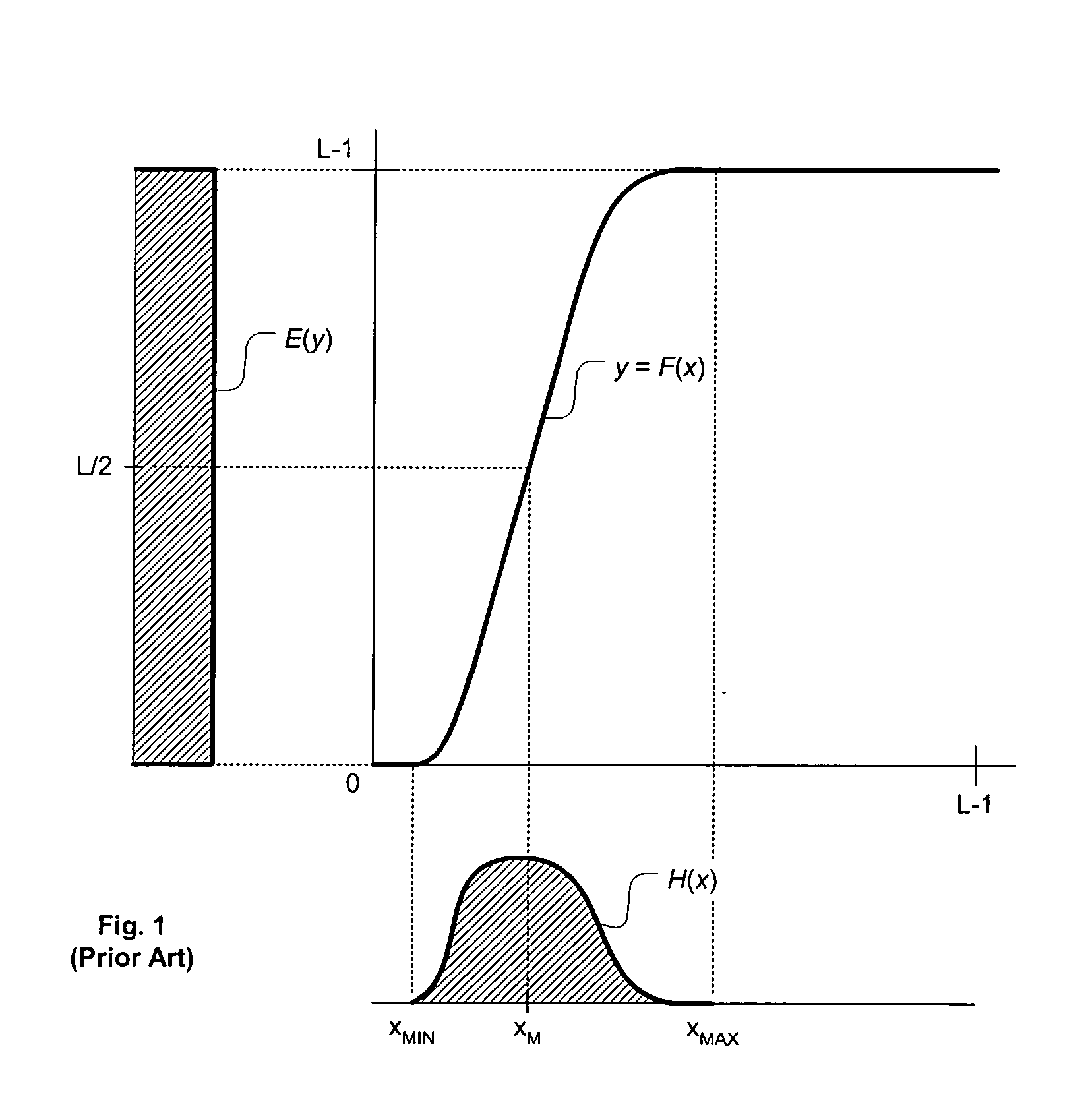
Second, the mean intensity is generally not a preferred metric for determining how an image should be equalized, as is evident from the discussion in the section above.
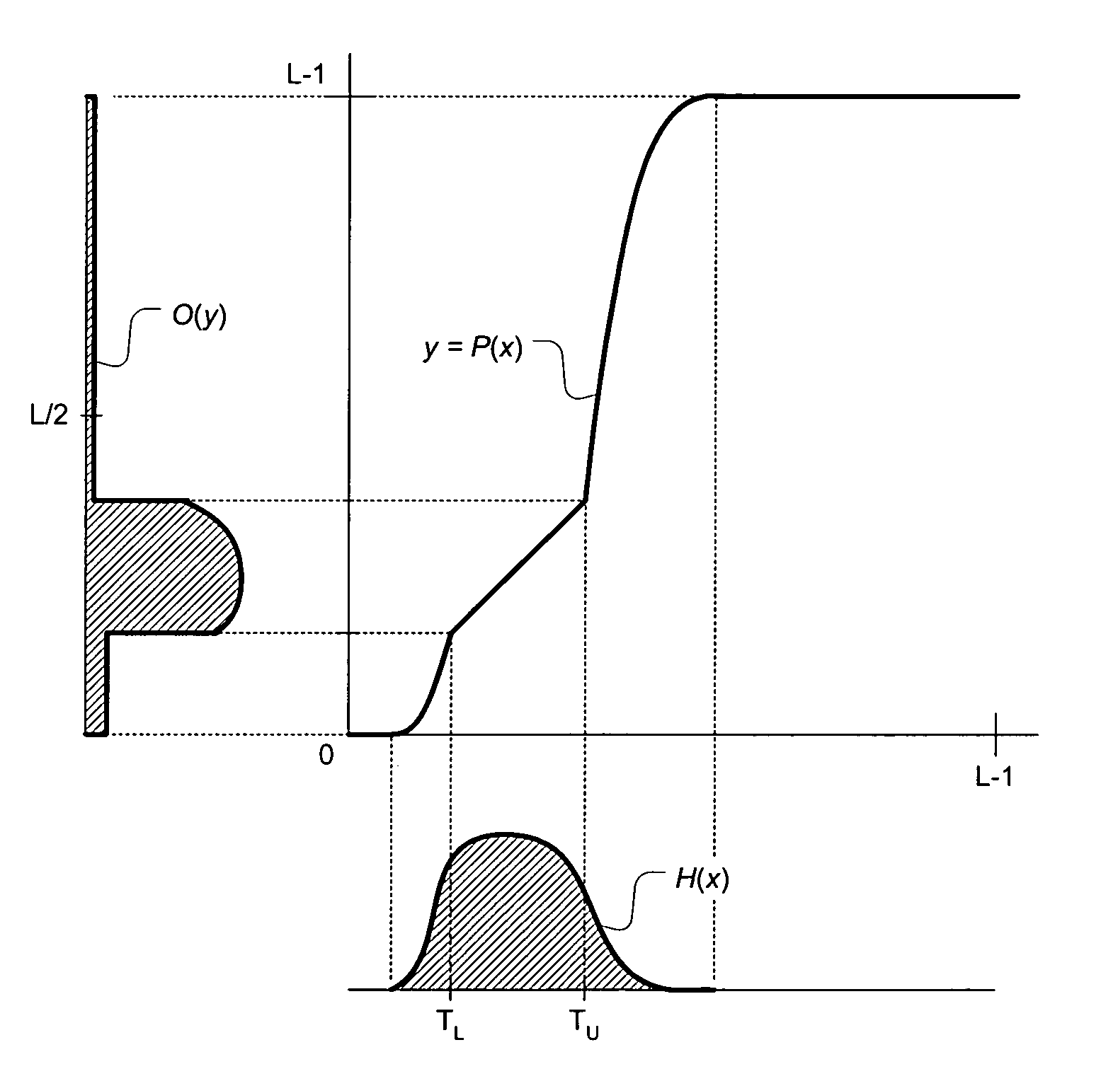
Although this approach may not provide the best contrast enhancement possible for each frame considered individually, it can provide good contrast enhancement without noticeable temporal intensity artifacts or lighting distortion.

Method used


Image

  • Video contrast enhancement through partial histogram equalization
  • Video contrast enhancement through partial histogram equalization
  • Video contrast enhancement through partial histogram equalization

Examples


Embodiment Construction

[0031]Several terms have been assigned particular meanings within the context of this disclosure. As used herein, the terms “above” and “below” a threshold are used with the recognition that, with integer comparisons, something is often defined to be “above” (or alternately, “below”) a threshold if it equals that threshold. A “contrast-enhancing function” redistributes a set of pixel intensities in a non-linear manner that increases the average contrast between neighboring intensities. A “function” can be a closed form equation, but a discrete function can also be implemented using, e.g., a lookup table. An “adaptive” function changes as scene content changes, although it need not change at every frame, and the response to scene content changes can be delayed or filtered. On the other hand, a “scene-stable” function remains substantially constant for the duration of a video scene (or longer); if such a function does change substantially, it does so at scene transitions or very gradu...


PUM


Abstract

Methods and apparatus for video contrast enhancement are disclosed. A pixel level threshold is set for an input video frame in a video sequence. For pixel levels in the input video frame that are below the threshold, an adaptive contrast-enhancing function is applied. For other pixel levels, a scene-stable mapping function is applied.This contrast enhancement method can improve the contrast in darker areas of a scene depicted in the video sequence, without destroying the intended light levels for a scene or causing temporal brightness fluctuations in the enhanced video sequence.

Description

FIELD OF THE INVENTION[0001]This present invention relates to video contrast enhancement, and more particularly to a method and apparatus for enhancing video contrast via partial histogram equalization.BACKGROUND OF THE INVENTION[0002]A digital image represents a visual scene as an array of pixels. Each pixel stores the image intensity level for a specific point in the visual scene. For example, in a black-and-white digital image, each pixel may contain an 8-bit value that expresses a luminance level as a number between 0 and 255, with 0 representing black and 255 representing white. In a color digital image, each pixel may have multiple components or color planes, each component representing the intensity level for a “color” (e.g., RGB (Red-Green-Blue) or CMY (Cyan-Magenta-Yellow) color planes) or a luminance / chrominance value.[0003]Many digital images are captured in such a way that the dynamic range available in the pixel format is underutilized. For instance, in a given 8-bit im...

Claims


Application Information

Patent Timeline
Patent Type & Authority Patents(United States)
IPC IPC(8): G06K9/00
CPCG06T5/009G06T5/40H04N21/44008H04N5/57H04N21/4318G06T2207/10016
Inventor KEROFSKY, LOUIS JOSEPH
Owner RAKUTEN GRP INC
Why Eureka
Try Eureka