Cable-stripping tool

a cable and tool technology, applied in the field of cable stripping tools, can solve the problem of limiting the possibility of cable movement, and achieve the effect of convenient and comfortable manoeuvr

Inactive Publication Date: 2006-02-28
PRESSMASTER
View PDF14 Cites 27 Cited by
  • Summary
  • Abstract
  • Description
  • Claims
  • Application Information

AI Technical Summary

Benefits of technology

[0007]Accordingly, one object of the invention is to provide a tool of the aforedescribed kind that can be readily and comfortably manoeuvred with one hand when placing the cable into the tool.

Problems solved by technology

The tool will also limit the possibility of movement of the cable along the support element.

Method used


Image

  • Cable-stripping tool
  • Cable-stripping tool
  • Cable-stripping tool

Examples


Embodiment Construction

[0028]Further scope of applicability of the present invention will become apparent from the detailed description given hereinafter. However, it should be understood that the detailed description and specific examples, while indicating preferred embodiments of the invention, are given by way of illustration only, since various changes and modifications within the spirit and scope of the invention will become apparent to those skilled in the art from this detailed description.

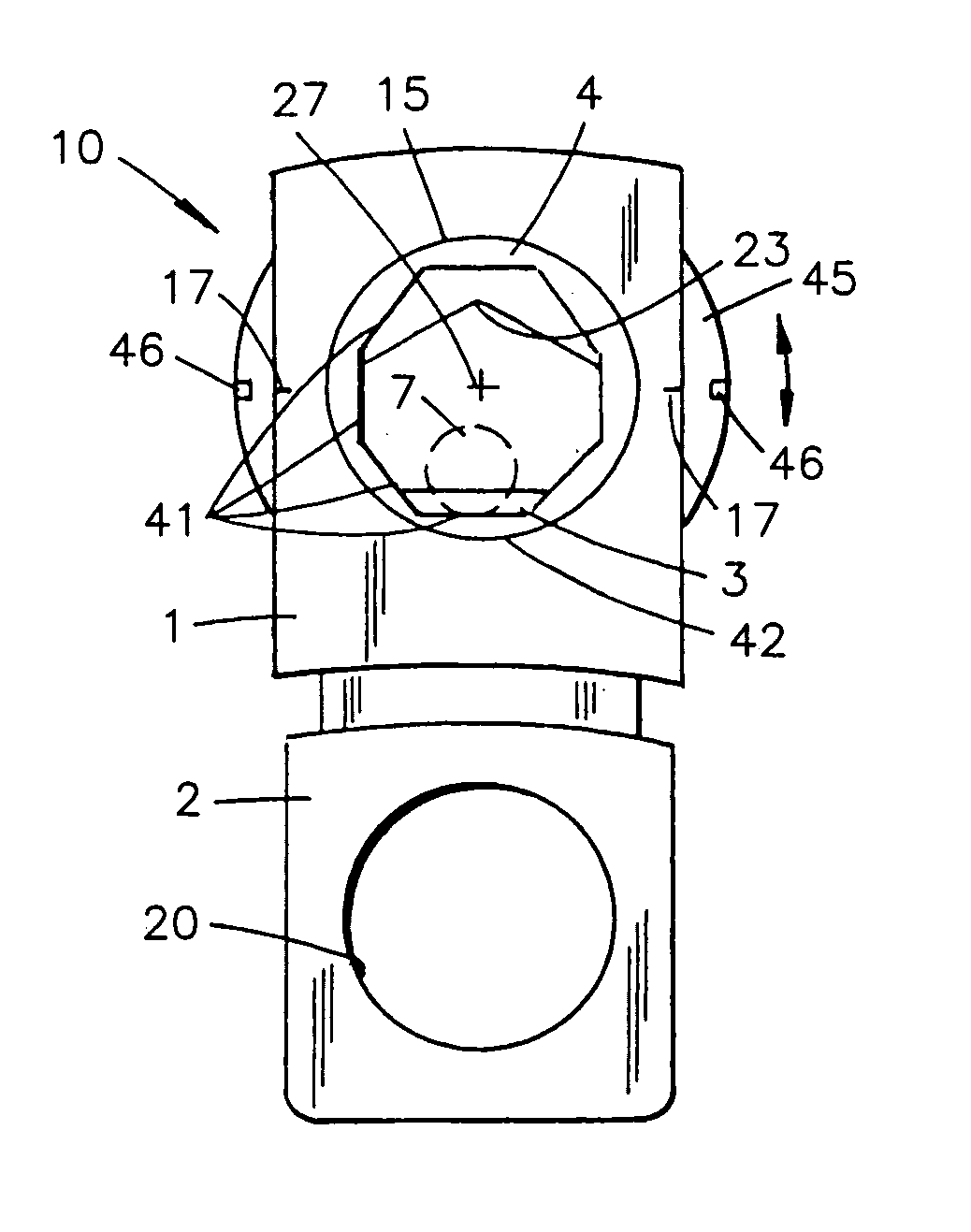
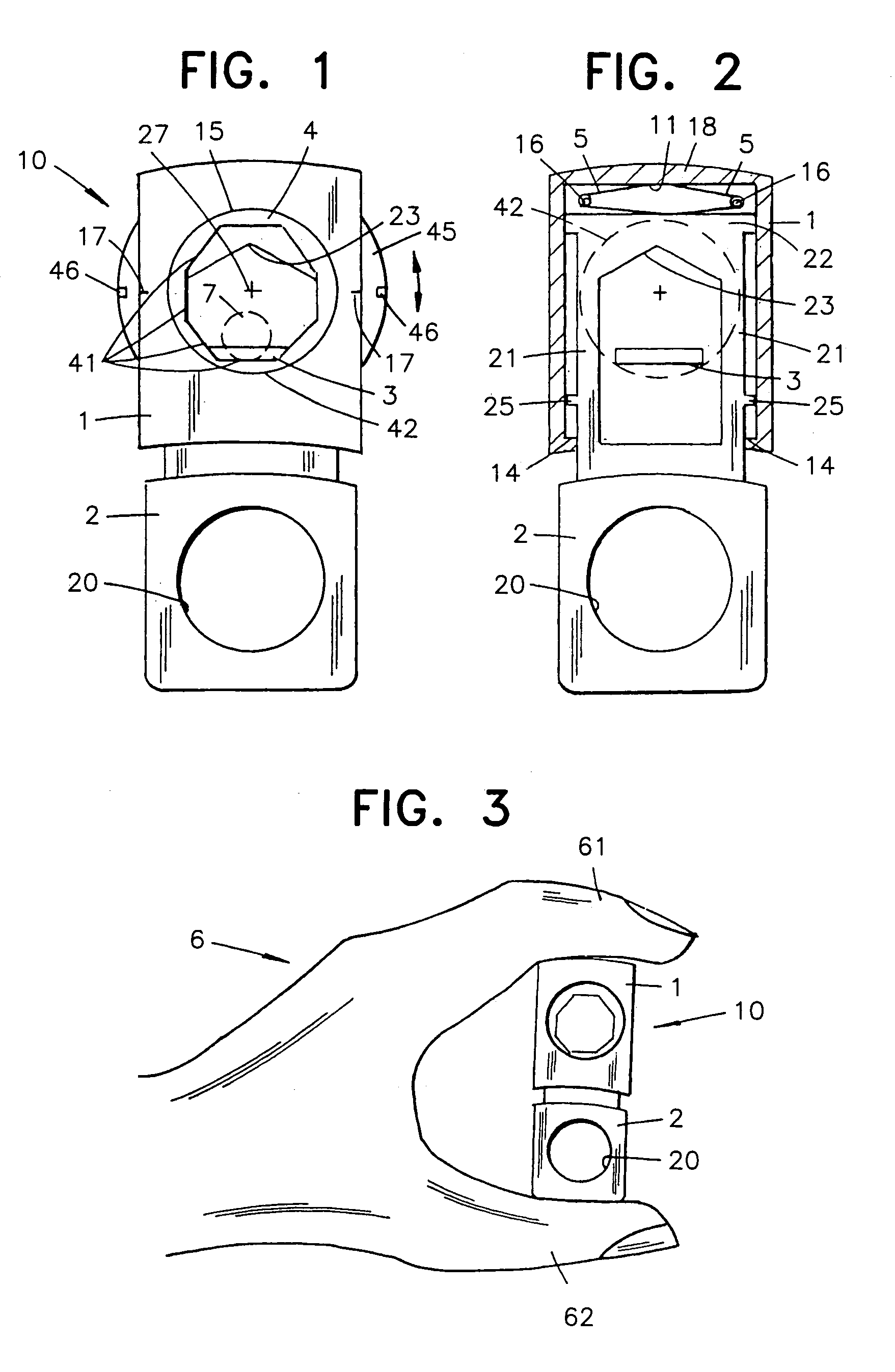
[0029]The tool 10 includes two main parts 1, 2 which are linearly movable in relation to one another, in a direction that stretches between the short ends of the tool. A ring 4 is rotatably mounted in one main part 1. The outer periphery 15 of the ring 4 is received in a corresponding opening 42 through the part 1. The ring 4 has an outwardly projecting peripheral flange 45 that includes markings 46 spaced peripherally around said flange and capable of being read against a read-off line 17 on the part 1. The flan...


PUM

PropertyMeasurementUnit
lengthaaaaaaaaaa
distancesaaaaaaaaaa
distanceaaaaaaaaaa

Abstract

A cable-stripping tool includes two parts that can be moved linearly in relation to each other, each of the parts including an opening which can accommodate a cable when the openings are in mutual alignment. The first part carries a cutting blade and has a support arrangement with a ring that, when rotated about an axis, adjusts a cutting depth of the blade. A spring element functions to bias the parts in a direction away from each other, while enabling the two tool parts to be brought together against the spring bias by a user squeezing with only one hand so that the cable to be stripped can be inserted into the tool intermediate the two ends to which force is applied.

Description

BACKGROUND OF THE INVENTION[0001]1. Field of the Invention[0002]The present invention relates to a cable-stripping tool.[0003]2. Description of the Related Art[0004]Known devices / tools for cable stripping are of a kind having first and second parts which are movable linearly towards and away from each other, a cutting blade which is carried by the first part, a support element which is carried by the first part, an abutment which is carried by the second part, and spring means which mutually bias the first and second parts in their relative movement directions. Using a through-passing opening provided for receiving a cable, such cable can be inserted between the abutment and the cutting blade when the first and second parts are mutually displaced in their respective directions against the bias of the spring element, such that the cable is clamped between the abutment on the one hand and the cutting blade on the other hand when the tool is relieved of load. The distance between the c...

Claims


Application Information

Patent Timeline
Patent Type & Authority Patents(United States)
IPC IPC(8): H02G1/12B26B27/00
CPCH02G1/1224
Inventor TAPPER, JOHAN
Owner PRESSMASTER
Why Eureka
Try Eureka