Unlock instant, AI-driven research and patent intelligence for your innovation.

System for aiding in prevention of engine overheating in a vehicle

a technology for engine overheating and vehicle, which is applied in vehicle heating/cooling devices, transportation and packaging, light and heating apparatus, etc. it can solve problems such as engine overheating, engine damage, and engine overheating, and achieve the effect of preventing automobile engine overheating

Inactive Publication Date: 2006-02-28
ABDELJAWAD ADEL A
View PDF5 Cites 13 Cited by
  • Summary
  • Abstract
  • Description
  • Claims
  • Application Information

AI Technical Summary

Benefits of technology

"The present invention provides a device to prevent automobile engine overheating. It uses a system that circulates liquid coolant between the engine and a radiator to absorb and remove heat. The system also includes an air duct system with a cool air conditioning device to cool air passing through it. The duct system has two outlets, one for exhausting air outside the vehicle and one for exhausting air inside the passenger compartment. The system also has two diverters that continuously direct heated air towards the first outlet and fresh or cool air towards the second outlet. The duct system also has a third outlet for exhausting air onto the engine. The invention helps prevent engine overheating and ensures efficient cooling of the engine."

Problems solved by technology

Such systems are not sufficient when operating under extreme hot or cold conditions, i.e., the liquid coolant may be too cold or get too hot.
If the coolant is too cold, the engine may run rough or stall and if the coolant is too hot, the engine may overheat and be damaged.
Overheating can occur on very hot summer days or when the motor vehicle is driven hard or in heavy traffic necessitating frequent stops and starts.
Overheating is also likely when the air conditioner is running adding additional load on the engine.
Overcooling can occur under extremely cold driving conditions.
This reduces the temperature of the circulating liquid coolant in hot weather at the expense of the passengers' comfort, particularly in hot summer conditions.

Method used


Image

  • System for aiding in prevention of engine overheating in a vehicle
  • System for aiding in prevention of engine overheating in a vehicle
  • System for aiding in prevention of engine overheating in a vehicle

Examples


Embodiment Construction

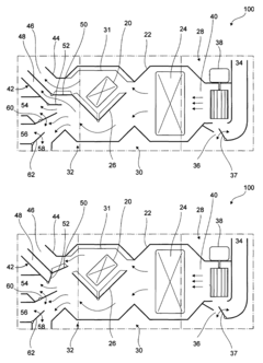
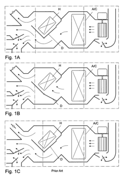
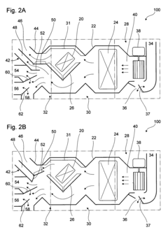
[0019]Referring to the drawings, the system for aiding in preventing automobile engine overheating is generally referred to by the reference numeral 100. Prior art is shown in FIGS. 1A–1C which depict various modes, wherein FIG.1 A indicates a heater core in “off mode” and cool air conditioner in “on mode” with a vent open only to permit cool air flow only to the passenger compartment, FIG. 1B indicates a heater core in “on mode” and cool air conditioner in “off mode” to provide heat with vent open only to permit hot air to the passenger compartment and FIG. 1C indicates a heater core in an “off mode” and cool air conditioner “on mode” with the vents open to permit cool air back to the engine and to a passenger compartment.

[0020]As a preface to discussing the invention, it is helpful to provide some description of a common internal combustion engine in an automobile having a liquid cooling system. Liquid coolant is circulated through a radiator and through passages in an engine bloc...


PUM


Abstract

A system for aiding an engine in a vehicle includes an air duct operably disposed in the vehicle having a fresh air inlet for receiving fresh air, first outlet for exhausting air outside the vehicle, and second outlet for exhausting air inside a passenger compartment, a cool air conditioning device operably disposed in the duct to cool air as it passes thereby when in an “on mode”, a heater core operably disposed in the duct to continuously provide heat air as it passes thereby and remove heat from the engine. A first diverter is operably disposed in the duct for continuously diverting at least some of the heated air toward the first outlet when the cool air conditioning device is in an “on mode” and a second diverter is operably disposed in the duct for continuously diverting at least one fresh air or cool air toward one of the outlets.

Description

FIELD OF THE INVENTION[0001]This invention relates to vehicle heating and cooling devices. More particularly, the invention relates to a system for aiding in preventing vehicle engine overheating.BACKGROUND OF THE INVENTION[0002]The temperature of a liquid cooled internal combustion engine is typically controlled by a liquid coolant circulated through the engine and a radiator. Currently, an attempt to control engine temperature is done through a system for controlling the temperature of the liquid coolant, typically by controlling the rate at which it circulates. Such systems are not sufficient when operating under extreme hot or cold conditions, i.e., the liquid coolant may be too cold or get too hot. If the coolant is too cold, the engine may run rough or stall and if the coolant is too hot, the engine may overheat and be damaged. Overheating can occur on very hot summer days or when the motor vehicle is driven hard or in heavy traffic necessitating frequent stops and starts. Ove...

Claims


Application Information

Patent Timeline
Patent Type & Authority Patents(United States)
IPC IPC(8): B60H1/00
CPCB60H1/00064B60H1/00842B60H2001/00178B60H2001/00107
Inventor ABDELJAWAD, ADEL A.
Owner ABDELJAWAD ADEL A