
Dual stage inflator with extended gas delivery for a vehicular airbag system

a vehicular airbag and inflator technology, applied in the field of systems and methods, can solve the problems of inability to maintain the pressure differential between the two chambers of the inflator, and achieve the effect of reducing manufacturing and installation costs, rapid, even and sustained inflation

Inactive Publication Date: 2006-02-28
AUTOLIV ASP INC
View PDF12 Cites 12 Cited by
  • Summary
  • Abstract
  • Description
  • Claims
  • Application Information

AI Technical Summary

Benefits of technology

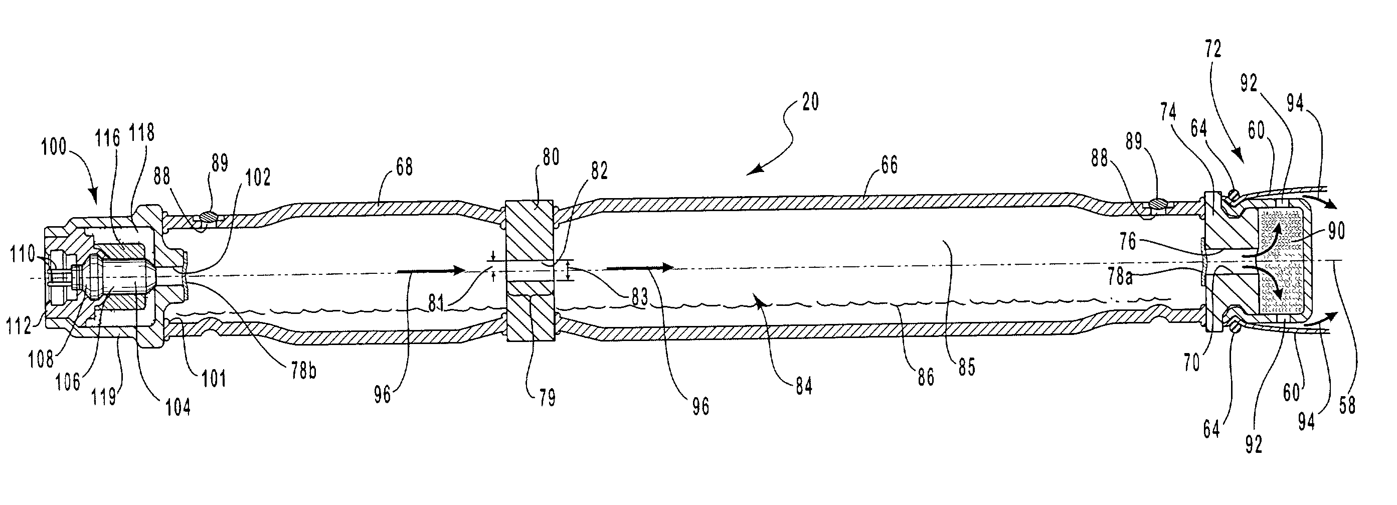
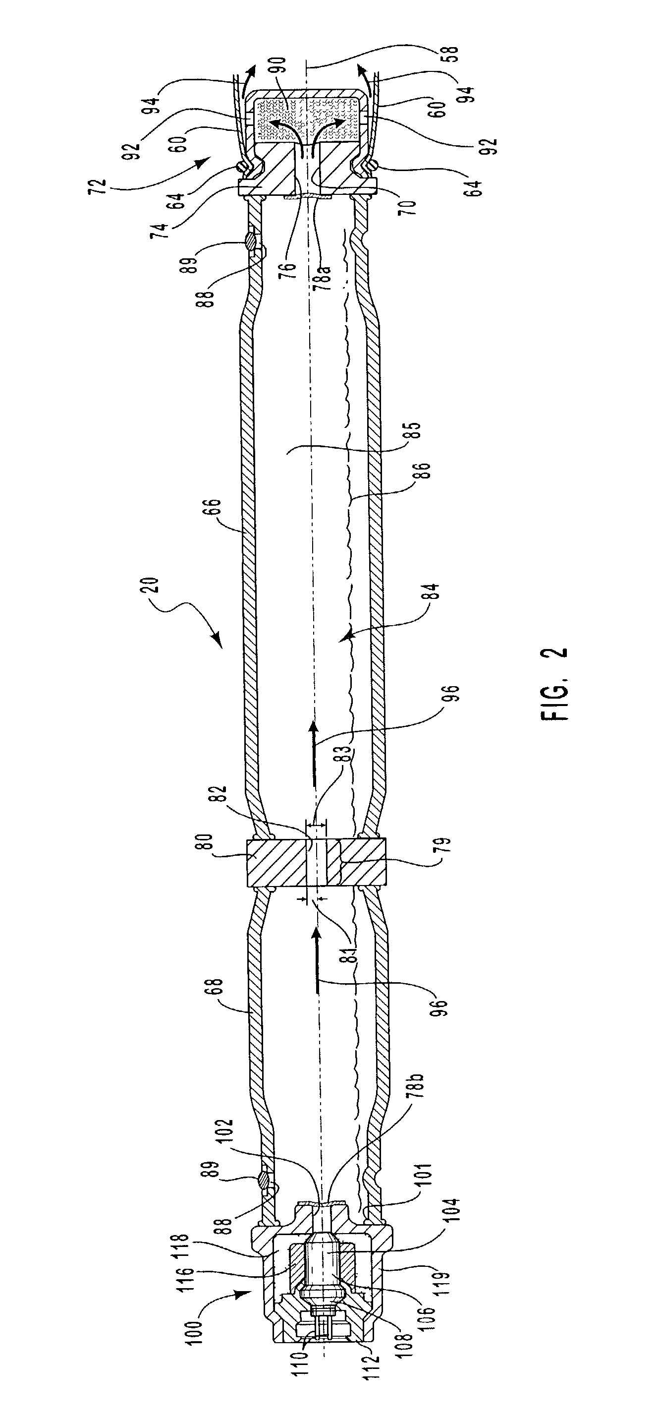
The present invention provides an inflator that can rapidly, evenly, and sustainably inflate an airbag while reducing manufacturing and installation costs. The inflator includes a first gas chamber with an exit orifice and an initiator to activate the inflation. It also includes a second gas chamber linked to the first chamber by a flow restrictor. The second gas chamber is in fluid connection with the first gas chamber through a restricted flow restrictor. The inflator may also include frangible seals to segregate the contents of each gas chamber from the outside environment. The inflator uses a liquefied gas that can be expanded to fill the airbag and provide additional inflation pressure. The invention also provides a method for producing an inflation charge for the inflator.

Problems solved by technology

In such inflators, a pressure differential may not be maintained between the two chambers of the inflator.

Method used


Image

  • Dual stage inflator with extended gas delivery for a vehicular airbag system
  • Dual stage inflator with extended gas delivery for a vehicular airbag system
  • Dual stage inflator with extended gas delivery for a vehicular airbag system

Examples


Embodiment Construction

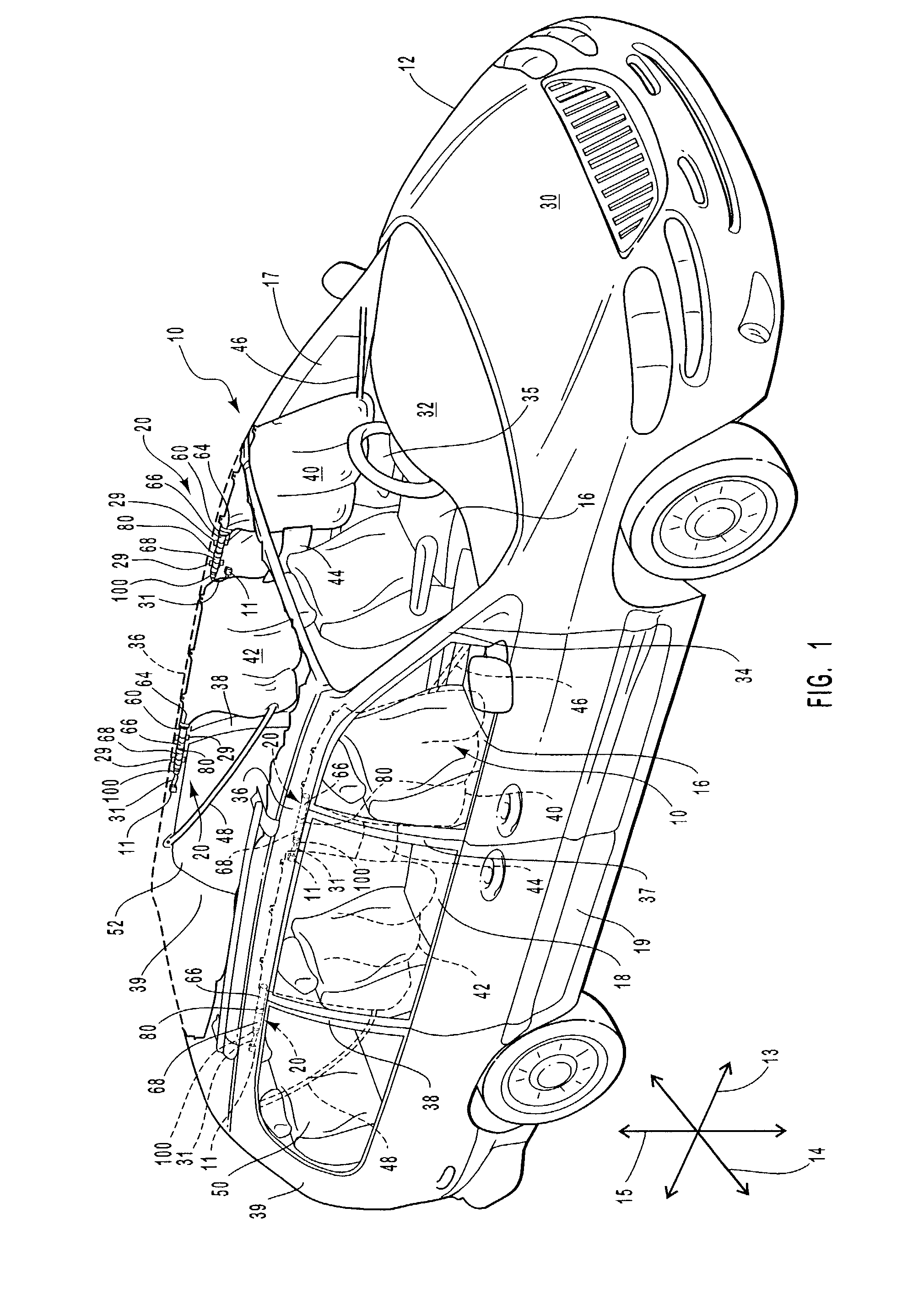
[0039]The presently preferred embodiments of the present invention will be best understood by reference to the drawings, wherein like parts are designated by like numerals throughout. It will be readily understood that the components of the present invention, as generally described and illustrated in the figures herein, could be arranged and designed in a wide variety of different configurations. Thus, the following more detailed description of the apparatus, system, and method of the present invention, as represented in FIGS. 1 through 4, is not intended to limit the scope of the invention, as claimed, but is merely representative of presently preferred embodiments of the invention.

[0040]The present invention provides an apparatus whereby problems associated with previously known inflators can be resolved. Through the use of axial flow, inflation gas can be injected into an airbag away from exit orifices of the inflator. Hence, the inflatable curtain deploys more evenly to provide ...


PUM


Abstract

A dual stage inflater for providing an extended flow of inflation gas to an airbag or inflatable curtain is disclosed. The inflator includes a first gas chamber having an exit orifice, the exit orifice having an open configuration and a closed configuration. Additionally, the inflator has a second gas chamber in gaseous communication with the first gas chamber. The first and second gas chambers are separated by a flow restrictor positioned between them. This restrictor controls the flow of gas out of the second gas chamber. The inflator includes an initiator in communication with the interior of one of the gas chambers that is configured to selectively initiate a flow of gas through the exit orifice of the first gas chamber. The exit orifice of the inflator may be disposed within an inlet port of an inflatable curtain to cause inflation gases exiting the inflator through the exit orifices to enter directly into the airbag or inflatable curtain.

Description

RELATED APPLICATIONS[0001]This application is a continuation-in-part of U.S. Ser. No. 10 / 115,857, filed Jun. 6, 2002, now U.S. Pat. No. 6,854,763 and entitled “Biaxial Flow Inflator With Independently Adjusted Gas Orifices,” and U.S. Ser. No. 10 / 100,820, filed Mar. 19, 2002, now U.S. Pat. No. 6,746,046 and entitled “Dual Flow Inflator for A Vehicular Airbag System,” and U.S. Ser. No. 10 / 100,928 filed Mar. 19, 2002, now U.S. Pat. No. 6,820,898 and entitled “Biaxial Dual Stage Inflator With Extended Gas Delivery For A Vehicular Airbag System.”BACKGROUND OF THE INVENTION[0002]1. Field of the Invention[0003]The present invention relates to systems and methods for protecting vehicle occupants from injury. More specifically, the present invention relates to a dual stage inflator for a vehicular airbag system that provides extended gas delivery by injecting multiple gas flows into an airbag system such as an inflatable curtain.[0004]2. Description of Related Art[0005]The inclusion of infla...

Claims


Application Information

Patent Timeline
Patent Type & Authority Patents(United States)
IPC IPC(8): B60R21/26B01J7/00B60R21/16B60R21/213B60R21/231B60R21/232B60R21/233B60R21/2338B60R21/261B60R21/263B60R21/264B60R21/268B60R21/272
CPCB60R21/232B60R21/26B60R21/264B60R21/272B60R21/213B60R2021/2685B60R2021/23386B60R2021/2612B60R2021/2615B60R2021/2633B60R2021/23107
Inventor DINSDALE, PAULGREEN, DAVID J.YOUNG, ANTHONY M.
Owner AUTOLIV ASP INC
Learn More