Ink-jet printhead

a technology of inkjet printing and printhead, applied in the field of inkjet printing, can solve the problems of increasing the component count of inkjet printinghead and requiring additional attachment work, and achieve the effect of convenient assembly

Active Publication Date: 2006-02-28
BROTHER KOGYO KK
View PDF9 Cites 38 Cited by
  • Summary
  • Abstract
  • Description
  • Claims
  • Application Information

AI Technical Summary

Benefits of technology

[0010]In the ink-jet printhead arranged as above, it is not necessary to additionally attach a separate ink filter to the in

Problems solved by technology

Generally, a separate plate-like filter is attached to the inlet of the ink supply channel for removing foreign matter from the ink flowing into the common ink supply chambers, since such foreign mat

Method used


Image

  • Ink-jet printhead
  • Ink-jet printhead
  • Ink-jet printhead

Examples


Embodiment Construction

[0026]Hereinafter, an piezoelectric type ink-jet printhead 100 according to an embodiment of the invention will be described with reference to the accompanied drawings.

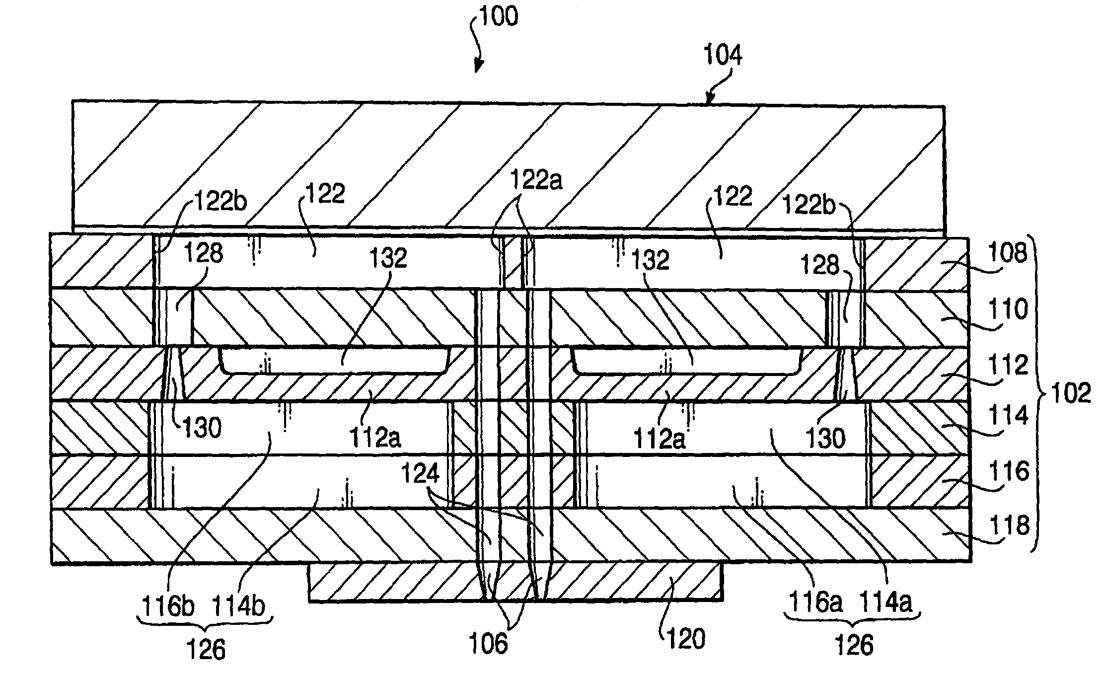
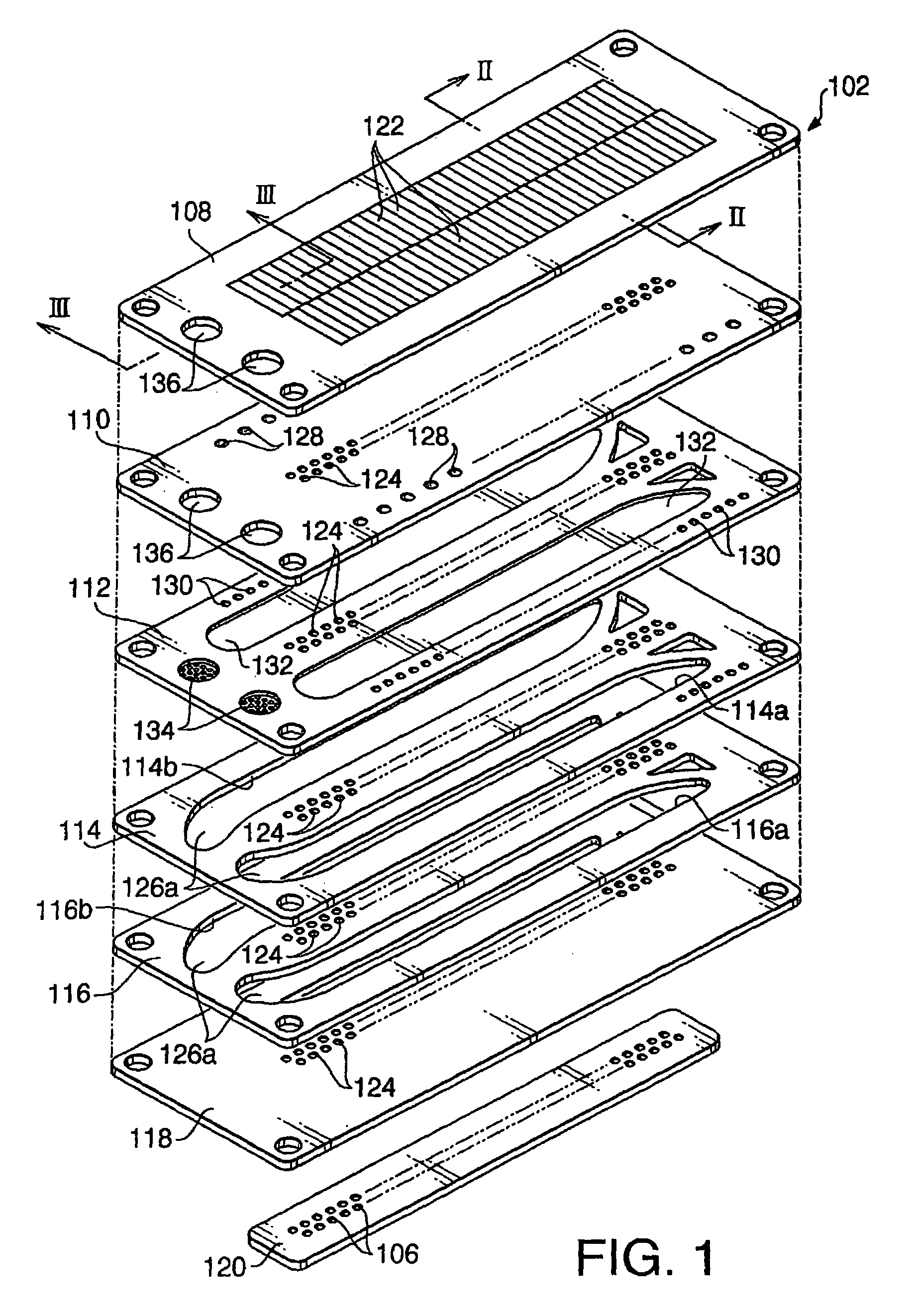
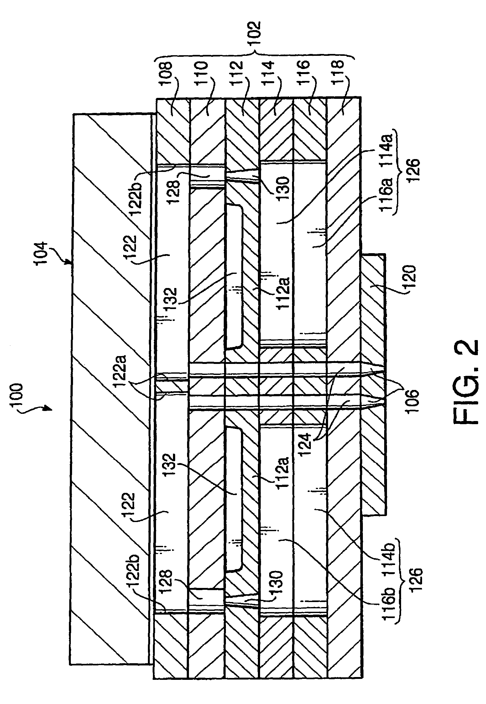
[0027]FIG. 1 is an exploded perspective view of a cavity unit 102 of the ink-jet printhead 100. FIGS. 2 and 3 are enlarged cross-sectional views of the ink-jet printhead 100 taken along lines II—II and III—III of FIG. 1, respectively.

[0028]As shown in FIGS. 2 and 3, the ink-jet printhead 100 includes a plate type piezoelectric actuator 104 mounted on the top of the cavity unit 102. The piezoelectric actuator 104 is connected with an external controller (not shown) through a flexible flat cable (not shown) connected to the upper surface of the piezoelectric actuator 104. The ink-jet printhead 100 is configured so as to eject ink downwards therefrom through a plurality of nozzle orifices 106 open toward the bottom of the cavity unit 102.

[0029]As shown in FIG. 1, the cavity unit 102 is formed from a plurality of thin pla...


PUM


Abstract

An ink-jet printhead includes a cavity unit and an actuator stacked together. The cavity unit is provided with a row of nozzle orifices and a row of pressure chambers communicating with the respective nozzle orifices. The actuator has a plurality of active portions for selectively actuating the respective pressure chambers to eject ink through the respective orifices. The cavity unit is a stack of plates including a cavity plate formed with the pressure chambers, a manifold plate formed with a manifold chamber and an intervenient plate interposed between the cavity plate and the manifold plate. The manifold chamber supplies ink from an external ink supply source to each of the pressure chambers. The intervenient plate is formed with a filter portion which filters ink provided from the external ink supplying source to the manifold chamber. The intervenient plate is formed with a damper wall facing the manifold chamber. The damper wall has a partial thickness of the intervenient plate.

Description

BACKGROUND OF THE INVENTION[0001]The present invention relates to an ink-jet printhead, and more particularly to an ink-jet printhead provided with a filter for removing foreign matter from ink.[0002]Japanese Patent Application Provisional Publication HEI 9-314836 discloses an ink-jet printhead having a laminated structure and actuated by a piezoelectric actuator on demand. The disclosed ink-jet printhead is constructed from substantially six plates stacked together in a laminated body. Assuming that the uppermost plate is the first plate and the lowermost one the sixth plate, the second plate sandwiched between the first and third plates is formed with a plurality of small openings that function as pressure generating chambers. The fifth plate sandwiched between the fourth and sixth plates is provided with a plurality of large openings that define common ink supply chambers.[0003]The common ink supply chambers are filled with ink supplied from an external ink tank, which ink is the...

Claims


Application Information

Patent Timeline
IPC IPC(8): B41J2/175B41J2/045B41J2/055B41J2/14
CPCB41J2/14209B41J2002/14419B41J2002/14403B41J2002/14225
Inventor ITO, ATSUSHI
Owner BROTHER KOGYO KK
Why Eureka
Try Eureka