
Method and computer program product for lighting a computer graphics image and a computer

a computer and graphics image technology, applied in the field of computer program products for lighting a computer graphics image, can solve the problems of increasing the apparent complexity of the surface, increasing the complexity and total computing time required for the rendering process, and increasing the complexity of the required rotation matrices. achieve the effect of improving the realism of the computer graphics image, avoiding image areas, and high efficiency

Active Publication Date: 2006-02-28
CRYTEK IP HLDG
View PDF13 Cites 28 Cited by
  • Summary
  • Abstract
  • Description
  • Claims
  • Application Information

AI Technical Summary

Benefits of technology

"The present invention provides a method for lighting a computer graphics image by pre-calculating the lighting conditions for the image. This method involves approximating the lighting conditions of the image by calculating the direction and color of the light sources illuminating the image. The method takes into account information about the object surface, such as the size and orientation of the object, and the distance of the viewer from the object. The method also allows for the storage and retrieval of the coefficients representing the lighting conditions for the image, which can be used for subsequent rendering. The method is efficient and flexible, and can be used in a variety of computer graphics applications."

Problems solved by technology

Bump mapping adds per-pixel surface relief shading, increasing the apparent complexity of the surface.
Computing the necessary rotation matrices requires substantial computing power.
A further problem associated with bump mapping of the above kind is that the complexity and total computing time required for the rendering process increases drastically with the total number of light sources illuminating the computer graphics image to be rendered.
At present, 3-D graphics cards with bump mapping are still not fast enough for more sophisticated lighting algorithms.

Method used


Image

  • Method and computer program product for lighting a computer graphics image and a computer
  • Method and computer program product for lighting a computer graphics image and a computer
  • Method and computer program product for lighting a computer graphics image and a computer

Examples


first embodiment

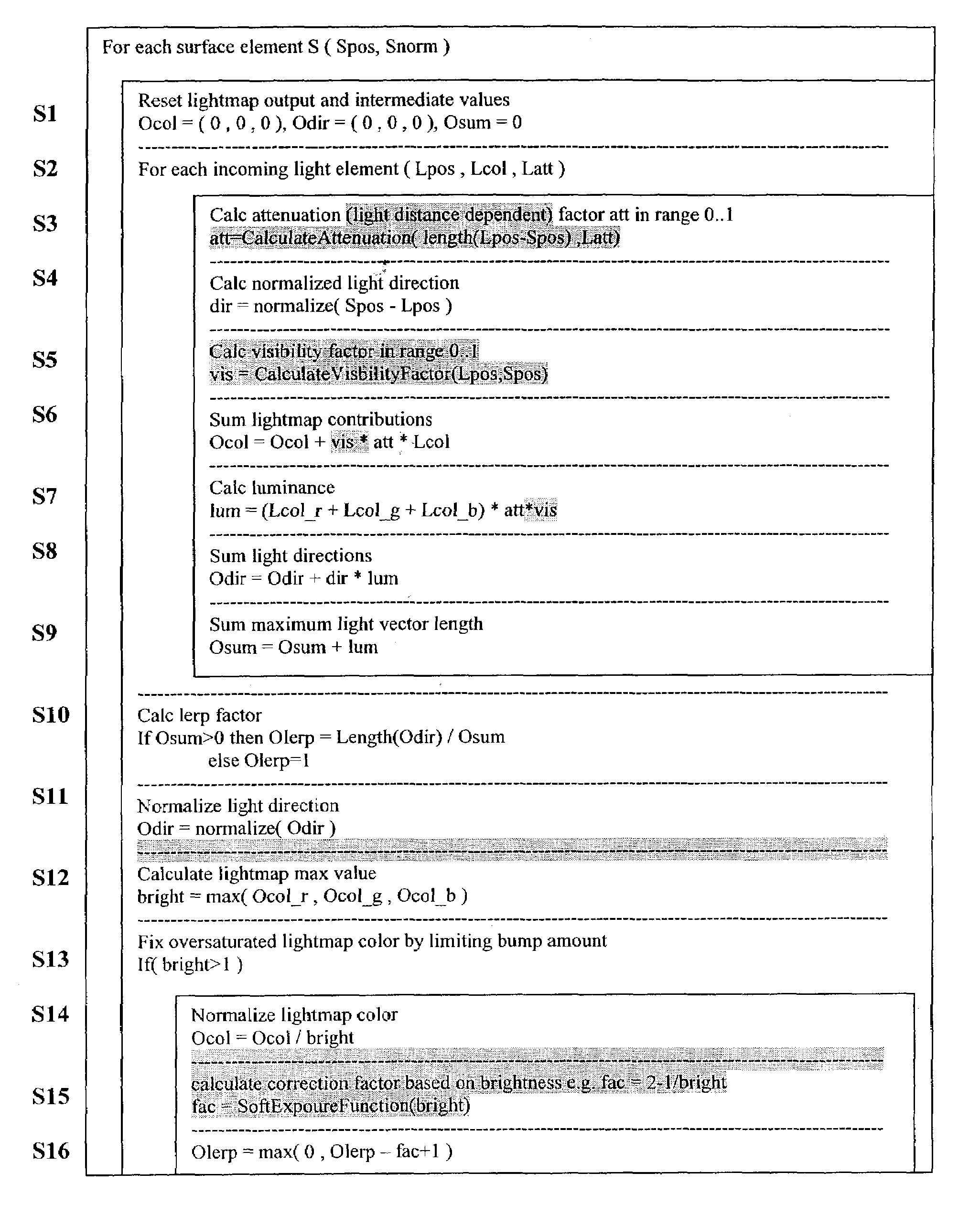
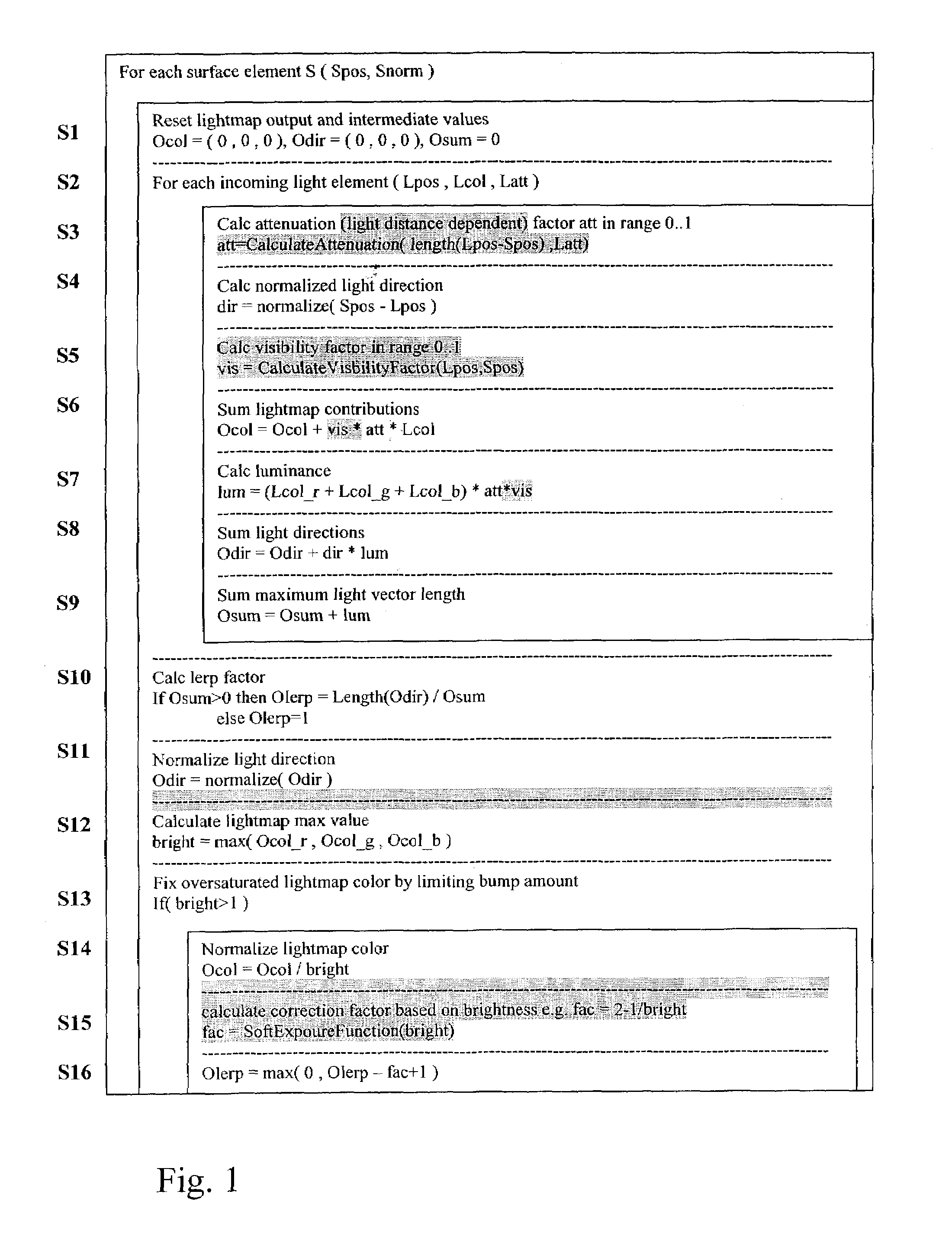
[0046]In the following a preferred example of a method according to a first embodiment of the present invention will be described with reference to FIG. 1. The process according to FIG. 1 is performed preferably as a pre-process, i.e. a procedure of pre-calculating, for compressing a complex lighting condition of a diffuse material. It is assumed that the object surface in the computer graphics image is illuminated by at least two light sources positioned at different positions in a three-dimensional space. From these light sources a subset of light sources is selected that are apt to illuminate the respective surface element to be processed and rendered. Hence, if objects are present in the light path between a respective light source and the surface element to be processed, such a light source is not necessarily taken into account for computing the complex lighting situation. Instead, such a light source can be neglected. A further example for selecting a subset of light sources a...

second embodiment

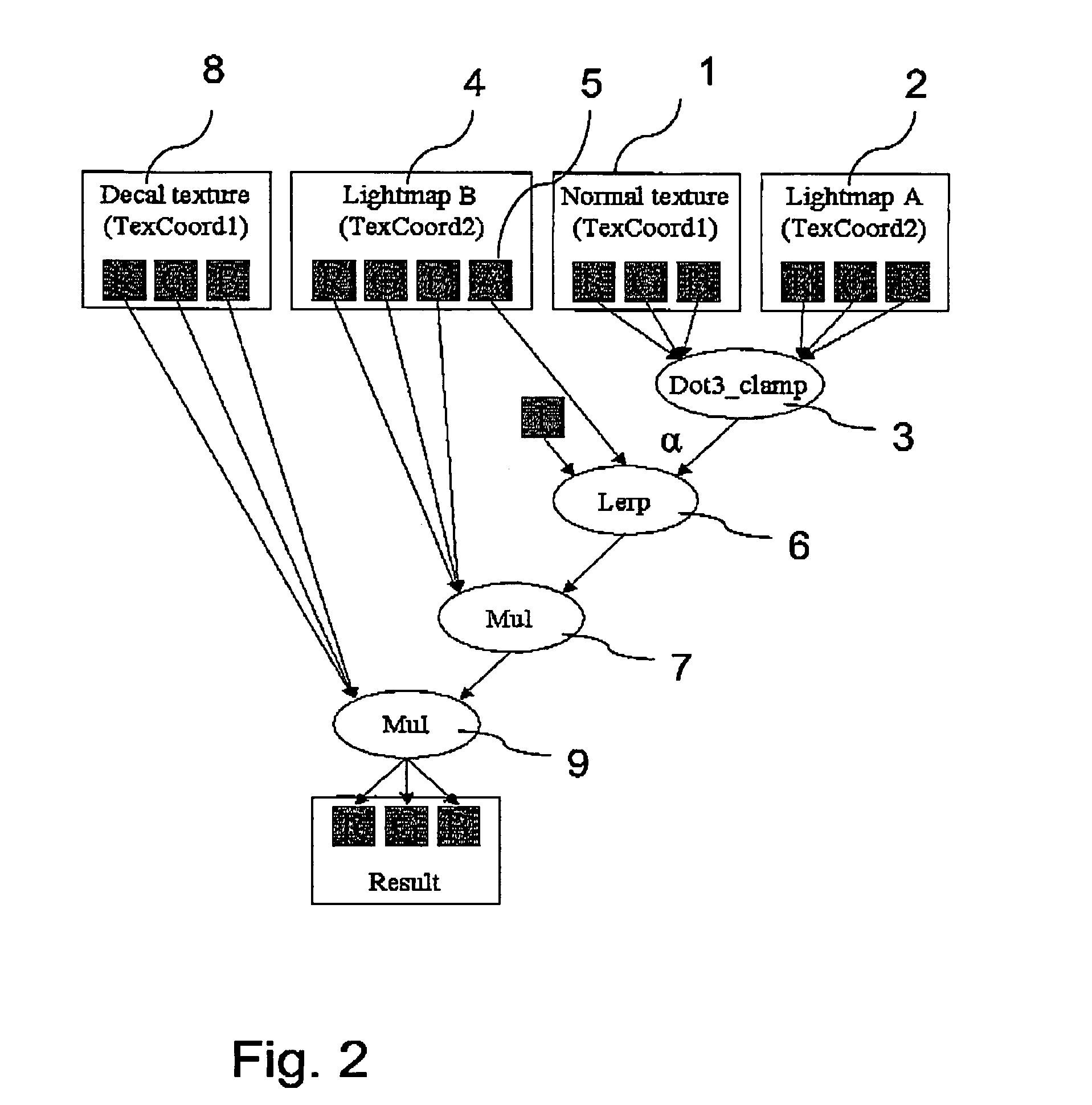
[0080]According to the first embodiment, the result of the approximation according to FIG. 2, which expressed in a compressed manner a complex lighting situation, is stored in two texture maps. The present invention is, however, not limited on such a storing scheme but may be implemented in a different manner.

[0081]Merely for illustrative purposes, in the following the basic principles of a second embodiment will be described. In the following it is assumed that the process of pre-calculating the complex lighting situation is performed in a substantially identical manner as the process described with reference to FIG. 1. However, according to the second embodiment the output of the above process of pre-calculating, namely the approximated light color, the approximated light direction and the blend factor between the lightmap and the high-resolution surface texture, is stored instead in vertex components of polygons building up the object surface to be rendered in three-dimensional s...

third embodiment

[0084]While the above process has been described with reference to pre-calculating complex lighting conditions in case of diffuse lighting, the present invention is by no way limited to pre-calculating diffuse lighting conditions. Instead, according to a third embodiment, which will be described in the following and may be combined with any of the other embodiments described in the specification, also complex lighting situations including specular reflection of light emanating from one or more light sources and being reflected by an object surface may be pre-calculated.

[0085]In addition to the above process of pre-calculating, for every stored light source the normalized light direction calculated in step S4 of the process according to FIG. 1 is used to calculate the half-angle vector (direction where the highlight is located) by normalizing the sum of the normalized light direction and the normalized eye direction.

[0086]For approximating the lighting situation a weight factor for w...


PUM


Abstract

The invention relates to a method to and a computer program product for lighting a computer graphics image to be rendered. It is assumed that a plurality of light sources illuminate one or more objects of the scene to be rendered thus causing a complex lighting situation. For reducing the complexity of the lighting situation and saving computing time the lighting condition is pre-calculated by approximating at least two and preferably all light sources by a single fictitious light source in a pre-calculating step. In the step of pre-calculating, there is computed an approximated light direction for at least two selected ones of the light sources and an approximated light color for the selected light sources by weighting color contributions thereof. The step of pre-calculating is performed for selected areas of a surface of objects present in the scene and results in coefficients that are stored, for these selected areas, in a lightmap or in vertices representing the object surface. The coefficients are retrieved by subsequent method steps for rendering the computer graphics image using the approximated light condition. The invention applies not only to diffuse lighting but is, with a minor modification, also of use for calculating specular lighting.

Description

FIELD OF THE INVENTION[0001]The present invention relates to a method to and a computer program product for lighting a computer graphics image, such as computer-generated images to be used in video games, computer games and computer-generated two- or three-dimensional images or sequences thereof. Furthermore, the present invention relates to a computer programmed to carry out the method of the present invention.BACKGROUND OF THE INVENTION AND RELATED ART[0002]In video game applications and the like computer-generated images are used for rendering a 3-D scene. For this purpose 3-D graphics cards are used. A common technique for adding realism to synthetic images without adding a lot of geometry is texture mapping. In texture mapping an object surface is computed as being composed of a plurality of geometric primitives, like polygons. A texture is cast onto the geometric object surface by filling the geometric primitives, like polygons, building up object surface.[0003]Recently real-t...

Claims


Application Information

Patent Timeline
Patent Type & Authority Patents(United States)
IPC IPC(8): G06T15/00G06T15/50
CPCG06T15/506
Inventor MITTRING, MARTIN
Owner CRYTEK IP HLDG
Learn More