Eureka AIR delivers breakthrough ideas for toughest innovation challenges, trusted by R&D personnel around the world.

Method and device for monitoring input optical power of avalanche photoelectric diode

A photodiode, avalanche photoelectric technology, applied in the direction of using electric radiation detectors for photometry, digital measurement technology for measurement, etc., can solve the problems of Iapd photocurrent difference and other problems, and achieve the effect of low cost

Inactive Publication Date: 2010-10-27
CHENGDU SUPERXON COMM TECH CO LTD
View PDF4 Cites 13 Cited by
  • Summary
  • Abstract
  • Description
  • Claims
  • Application Information

AI Technical Summary

Problems solved by technology

However, because the avalanche photodiode is very sensitive to several external environmental factors such as Vapd bias voltage and ambient temperature, it is known that the Iapd photocurrent output by the avalanche photodiode is different under the same input optical power value but different Vapd bias voltage. The Iapd photocurrent output by the avalanche photodiode is also different under the same input optical power value and the same Vapd bias voltage but different temperatures, and the Iapd photocurrent value output by the avalanche photodiode under the same Vapd bias voltage and the same temperature The input optical power value is a non-linear relationship, and complex formulas are required to convert the Iapd photocurrent value (actually the digital quantity of the mirror current Iapd1) into the input optical power value
Therefore, the accuracy of traditional input optical power monitoring with avalanche photodiodes, according to the SFF-8472 protocol, combined with the test data of actual mass production, within the commercial temperature range of 0 degrees Celsius to 70 degrees Celsius, the error can only be controlled within + / -3dB , 3dB means that the difference between the monitored value and the actual value is half, which is an almost intolerable error for optical communication systems

Method used


Image

  • Method and device for monitoring input optical power of avalanche photoelectric diode
  • Method and device for monitoring input optical power of avalanche photoelectric diode
  • Method and device for monitoring input optical power of avalanche photoelectric diode

Examples


Embodiment Construction

[0026] The technical solutions of the present invention will be further described below in conjunction with the accompanying drawings and through specific implementation methods.

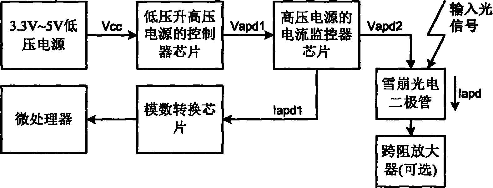
[0027] image 3 It is a traditional system connection diagram for monitoring the input optical power with an avalanche photodiode. Figure 4 It is a schematic diagram of a device for monitoring the input optical power of an avalanche photodiode of the present invention. The device for monitoring the input optical power of the avalanche photodiode of the present invention lacks a current monitor chip of a high-voltage power supply, and its system connection mode is very similar to the traditional connection mode. Such as Figure 4 Shown, the present invention is a novel receiver optical subassembly (ROSA), and the novel receiver optical subassembly further includes an avalanche photodiode (APD), a transimpedance amplifier (optional), a planar optical waveguide splitter ( PLC SPITTER), a linear pho...


PUM


Abstract

The invention discloses a method and a device for monitoring the input optical power of an avalanche photoelectric diode, and provides a novel ROSA; a planar optical waveguide splitter splits a received input optical signal into two circuits, wherein one circuit of light with high optical power is distributed to the traditional avalanche photoelectric diode of an optical receiver and is applied to an original optical receiver, and the other circuit of light with low optical power is distributed to a linear photoelectric diode for improving the monitoring precision to the input optical power. The technical scheme can reduce the cost and the complicacy of a monitoring system to the input optical power of the traditional avalanche photoelectric diode in the optical receiver, and improve the monitoring precision to the input optical power.

Description

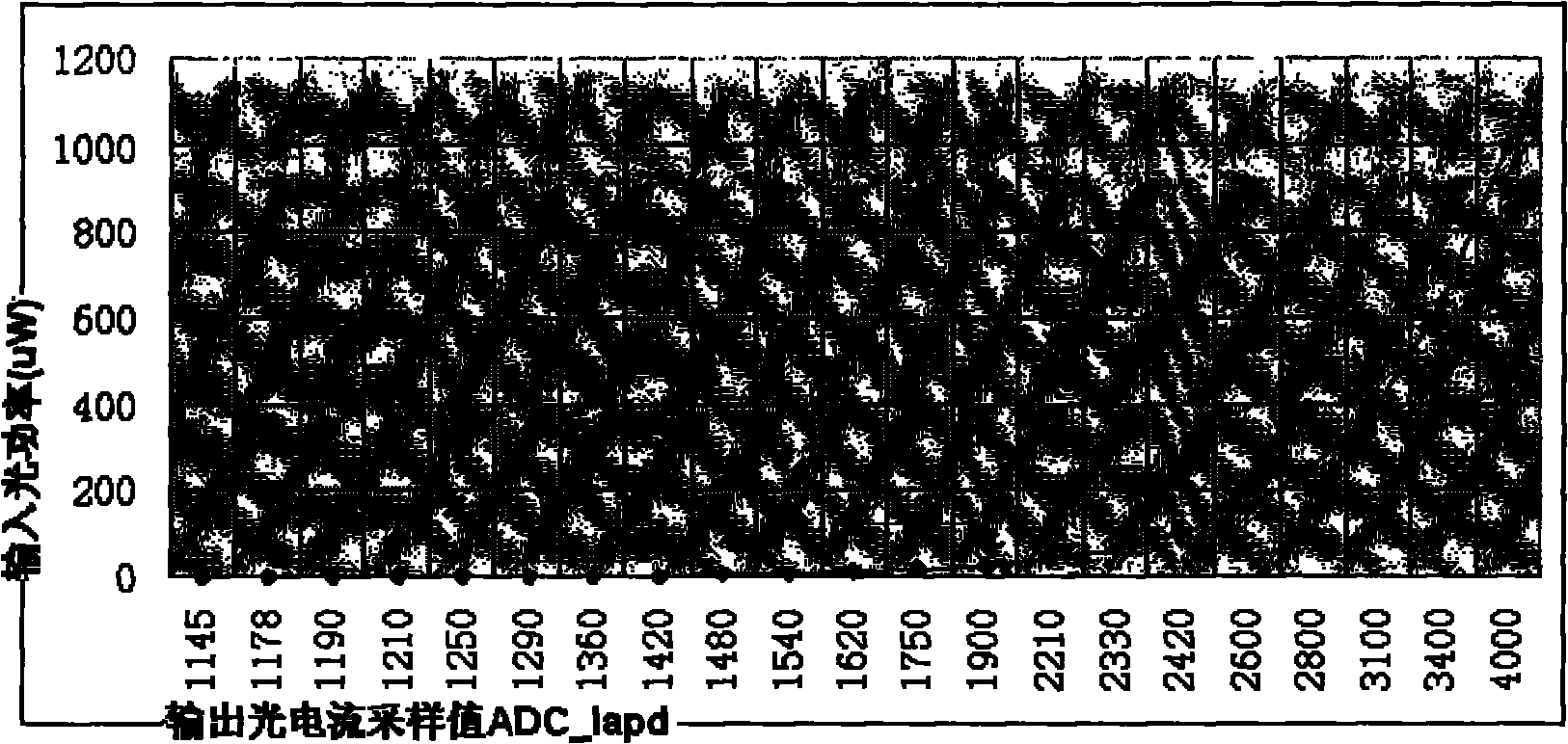
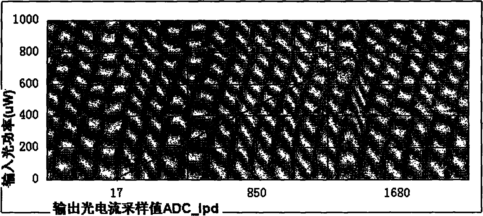
technical field [0001] The invention relates to the technical fields of optics and electronic engineering, in particular to a method and device for monitoring the input optical power of an avalanche photodiode. Background technique [0002] The traditional optical receiver monitors the input optical power of its APD avalanche photodiode by using the current monitor chip of the high-voltage power supply to measure the photocurrent Iapd flowing through the avalanche photodiode, that is, the output photocurrent Iapd of the current monitor chip Mirror the current Iapd1, and then use an ADC analog-to-digital converter to sample the mirror current Iapd1 and convert it into a digital quantity. In the case of different input optical power, by sampling different values ​​ADC_Iapd of the photocurrent Iapd flowing through the avalanche photodiode, a graph is formed, such as figure 1 , where the horizontal axis is the sampling value of the 12-bit ADC of Iapd, and the vertical axis is t...

Claims


Application Information

Patent Timeline
IPC IPC(8): G01J1/42G01R19/25
Inventor 张亮蒋建明刘勇
Owner CHENGDU SUPERXON COMM TECH CO LTD
Why Eureka
Eureka Blog
Learn More