Cylinder-pressure-based electronic engine controller and method

a technology of electronic engine controller and cylinder pressure, which is applied in the direction of electric control, machines/engines, instruments, etc., can solve the problems of large volume of data generated, large volume of cylinder pressure data may exceed the computing capability of internal combustion engine controllers utilized for controlling internal combustion engines, and inability to quickly process large amounts of data utilizing “on-board” controllers, so as to save computing capacity

Active Publication Date: 2009-10-20
DELPHI TECH IP LTD
View PDF5 Cites 16 Cited by
  • Summary
  • Abstract
  • Description
  • Claims
  • Application Information

AI Technical Summary

Benefits of technology

[0005]The present invention interfaces to multiple cylinder pressure sensors located at each cylinder of an internal combustion engine to evaluate cylinder combustion events. Sensor outputs are converted to angle based cylinder pressure samples via high speed analog to digital (A / D) converters. An angular position sensing element such as an encoder connected to a rotating engine component provides an angular reference of the position of the moving engine components (i.e. angular position within the 720° engine cycle). The crank angle information from the angular position sensing element is utilized to trigger the A / D converters and thereby sample pressure data from the cylinder pressure sensors in the angle domain. Crank angle information may be used to synthesize high angle resolutions from a lower resolution angular position sensing element (e.g. encoder) and thereby sample the cylinder pressure sensors at high angular sample rates. The conversion results from each A / D converter are transferred to a microcontroller via four Serial Peripheral Interface (SPI) ports, and Direct Memory Access (DMA) features within the microcontroller transfer the conversion results to pre-defined memory buffers without Central Processing Unit (CPU) intervention, thus saving computing capacity for use in doing other calculations.
[0006]Because the cylinder pressure data measured during the combustion event is of primary importance for determining combustion parameters, higher resolutions of angle based samples are required. Cylinder pressure data from other portions of the engine cycle are less critical to making the combustion parameter calculations and therefore can utilize samples at lower angle based resolutions. The present invention provides for user-defined “windows” corresponding to different portions of an engine cycle to allow variable angle based sample rates of cylinder pressure data during one engine cycle. Different angular resolutions for cylinder pressure data can be specified in each of the windows. This allows data samples of maximum resolution in portions of the engine cycle where combustion occurs and less resolution in less critical portions of the engine cycle, thereby substantially reducing the amount of data utilized for combustion parameter calculations.
[0007]Data from a particular cylinder can be processed during the portions of the cycle following a combustion event, and utilized to control parameters such as the volume and timing of fuel supplied to the cylinder, timing of the spark, and the like in the very next engine cycle of that cylinder. The present invention provides a way to accurately measure the cylinder pressure at very small crank angles during the combustion event, and the various combustion parameters needed for control can be calculated and utilized for control of the cylinder in the very next engine cycle. In this way, the combustion occurring in each cylinder can be very closely monitored and utilized for real-time control of the engine.

Problems solved by technology

However, if cylinder pressure readings are taken at very short time intervals / small crank rotation angular increments, a very large volume of data is generated.
Because the various combustion parameters need to be calculated from the raw pressure data, a very large volume of cylinder pressure data may exceed the computing capability of controllers utilized for control of internal combustion engines.
The inability to quickly process large amounts of data utilizing an “on-board” controller typically precludes use of high resolution data for closed-loop engine control.

Method used


Image

  • Cylinder-pressure-based electronic engine controller and method
  • Cylinder-pressure-based electronic engine controller and method
  • Cylinder-pressure-based electronic engine controller and method

Examples


Embodiment Construction

[0020]For purposes of description herein, the terms “upper,”“flower,”“right,”“left,”“rear,”“front,”“vertical,”“horizontal,” and derivatives thereof shall relate to the invention as oriented in FIG. 1. However, it is to be understood that the invention may assume various alternative orientations and step sequences, except where expressly specified to the contrary. It is also to be understood that the specific devices and processes illustrated in the attached drawings and described in the following specification are simply exemplary embodiments of the inventive concepts defined in the appended claims. Hence, specific dimensions and other physical characteristics relating to the embodiments disclosed herein are not to be considered as limiting, unless the claims expressly state otherwise.

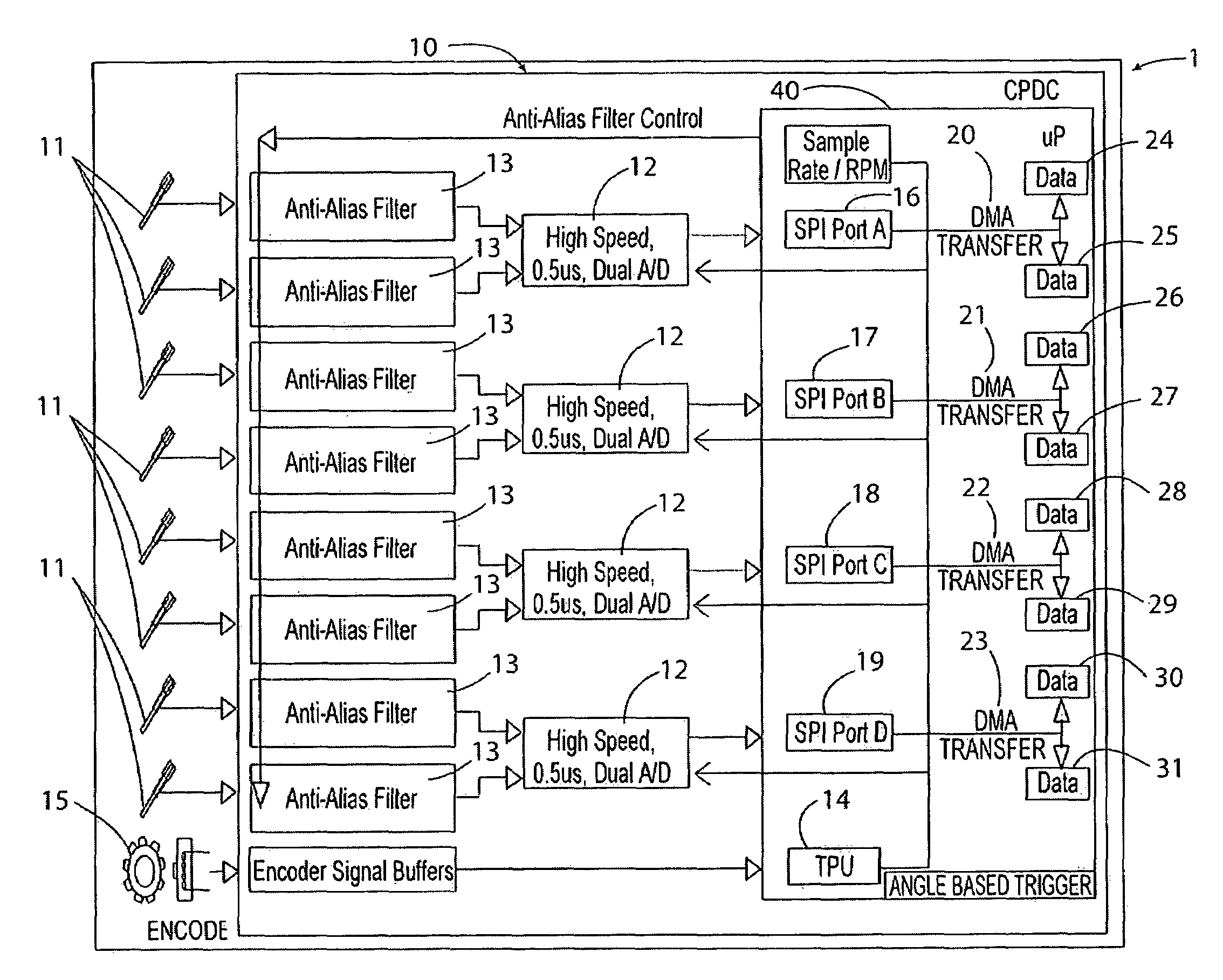
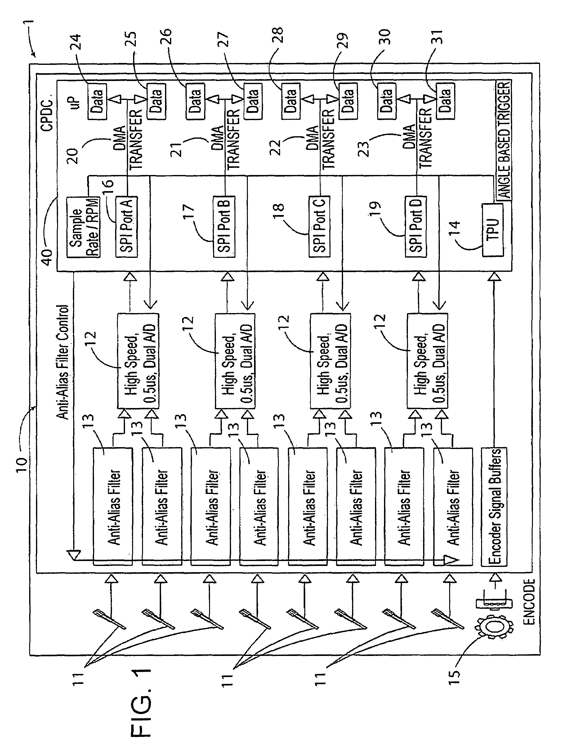
[0021]With reference to FIG. 1, a control system 1 includes a Cylinder Pressure Development Controller (CPDC) 10 having a plurality of cylinder pressure measurement channels that are operably connected...


PUM


Abstract

An engine data acquisition and control system measures cylinder pressure at a high degree of resolution and then processes it for portions of the combustion cycle of interest for performing combustion calculations. The data are utilized to calculate combustion parameters, and the combustion parameters may be utilized to control the engine's fuel and / or spark timing / duration, and other variables affecting the combustion process. The system architecture provides for acquisition of very large amounts of data without unduly loading the CPU.

Description

CROSS-REFERENCE TO RELATED APPLICATION[0001]This application claims the benefit of U.S. Provisional Patent Application No. 60 / 848,290, filed on Sep. 29, 2006, the entire contents of which are incorporated herein by reference.TECHNICAL FIELD[0002]The present invention is related to control of internal combustion engines utilizing cylinder pressure measurements.BACKGROUND OF THE INVENTION[0003]The cylinder pressures of an internal combustion engine can be measured and utilized to determine key information about the engine's operation. Cylinder pressure measurements can be utilized to calculate combustion parameters such as Indicated Mean Effective Pressure (IMEP), Start of Combustion (SOC), total Heat Release (HRTOT), the crankshaft angles at which 50% and 90% of the total heat release have occurred (HR50, HR90), and the crankshaft angle Location of Peak Pressure (LPP).[0004]High resolution cylinder pressure readings provide for more accurate combustion parameter calculations. However...

Claims


Application Information

Patent Timeline
Patent Type & Authority Patents(United States)
IPC IPC(8): G06F19/00G01M15/00
CPCF02D35/023F02D41/266F02D41/28F02D35/028F02D2041/285F02D2250/12F02D2250/14F02D2041/1432
Inventor HUSTED, HARRY L.ERICKSON, CLINTON W.PUNATER, ASHISH DSCHTEN, KARL A.KILGOUR, GERALD ACONYERS, MICHAEL P.
Owner DELPHI TECH IP LTD
Why Eureka
Try Eureka