Supercharge Your Innovation With Domain-Expert AI Agents!

Pathlength matched beam splitter and method and apparatus for assembly

a beam splitter and pathlength matching technology, applied in the field of assembly of beam splitter cubes and polarizing beam splitter cubes, can solve the problems of additional labor, increased production costs, and increased production costs of other optical assemblies, and achieves low operator skill, high yield, and high volume production

Inactive Publication Date: 2006-02-28
LIGHTMASTER SYST
View PDF44 Cites 0 Cited by
  • Summary
  • Abstract
  • Description
  • Claims
  • Application Information

AI Technical Summary

Benefits of technology

"The present invention provides a method and device for constructing a pathlength matched optical device. The method involves matching the optical paths of prism components used in the device, and using an adhesive to hold the components in place. The device includes a holding device and an adjustment device to accurately align the components. The invention allows for faster, easier, and higher yield production of pathlength matched optical devices, making it more cost-effective for high-volume production. The invention can be implemented using computer programming and can be transmitted to remote devices for output or display."

Problems solved by technology

This is due to the fact that most individual prisms are not produced to a high physical tolerance and that variations are not normally accommodated in the PBS assembly process.
One example of such an optical assembly is disclosed in the above-referenced patent application entitled “METHOD AND APPARATUS FOR CONFIGURATION AND ASSEMBLY OF A VIDEO PROJECTION LIGHT MANAGEMENT SYSTEM.” However, this and other optical assemblies generally require costly PBS production techniques.
This method can produce a pathlength matched PBS but requires the additional labor associated with the measurements and provides additional opportunity to damage delicate prism surfaces.
In practice, this fabrication method is found to be slow, require considerable operator skill, and provides a poor yield.

Method used


Image

  • Pathlength matched beam splitter and method and apparatus for assembly
  • Pathlength matched beam splitter and method and apparatus for assembly
  • Pathlength matched beam splitter and method and apparatus for assembly

Examples


Embodiment Construction

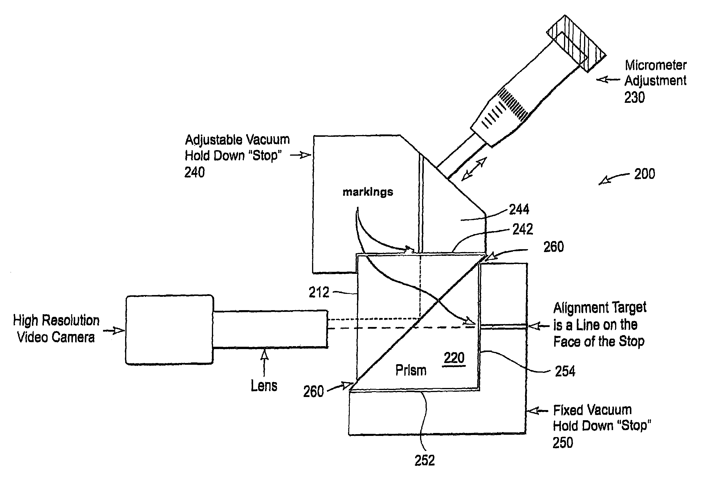
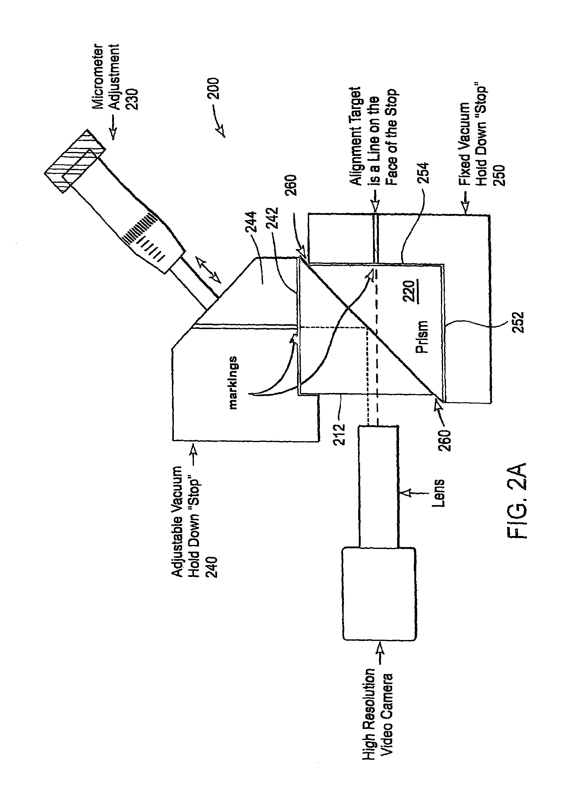
[0021]Referring again to the drawings, wherein like reference numerals designate identical or corresponding parts, and more particularly to FIG. 2 thereof, there is illustrated a pathlength matching device 200 used to produce a pathlength matched PBS or beam splitting cube. A production process of a pathlength matched PBS cube is now described.

[0022]The pathlength matching device 200 is configured to hold two prisms (e.g., prism 210 and 220) and provide a fine adjustment (e.g. micrometer adjustment 230) for aligning or matching selected pathlengths through the two prisms. The two prisms (210 and 220) that will compose a PBS upon completion of the production process are positioned onto precision “stops” (240, 250) of the pathlength matching device 200. Using the terminology defined in FIG. 1, Face 1 (on the top prism 210) is attached to the adjustable stop 240 along side 242, and Face 2 (on the side of prism 220) is attached to the fixed stop 220 along side 252.

[0023]One method to ac...


PUM


Abstract

Pathlength matched optical devices (such as beam splitters) are produced by viewing optical paths through the optical devices and adjusting relative positions of optical components of the optical devices until the viewed optical paths are equivalent. The optical paths begin at markings at different locations on the optical device. The optical pathlengths are equivalent when both markings are in focus in a limited field of view camera or lens. In a beam splitting cube constructed of two prisms, markings located at precisely similar locations on different prisms are pathlength matched when coincident as viewed at a reference face of the cube. The prisms are abutted at their diagonals and are adjusted by sliding the prisms along the diagonals to the pathlength matched position. Optical adhesive between the prisms is cured after fixing the prisms at the pathlength matched position.

Description

CROSS REFERENCE TO RELATED APPLICATIONS AND CLAIM OF PRIORITY[0001]This invention is a division of Ser. No. 10 / 251,225 filed Sep. 20, 2002 now U.S. Pat. No. 6,808,874 which claims priority to the following co-pending U.S. provisional patent application, which is incorporated herein by reference, in its entirety:[0002]Detro, Provisional Application Ser. No. 60 / 349,273, entitled “A Means of Assembling a “Pathlength Matched” PBS Cube,” filed, Jan. 14, 2002.[0003]This application also makes reference to Detro et al., U.S. patent application Ser. No. 10 / 202,595, entitled “METHOD AND APPARATUS FOR CONFIGURATION AND ASSEMBLY OF A VIDEO PROJECTION LIGHT MANAGEMENT SYSTEM,” filed Jul. 24, 2002 the contents of which are incorporated herein by reference in its entirety.COPYRIGHT NOTICE[0004]A portion of the disclosure of this patent document contains material which is subject to copyright protection. The copyright owner has no objection to the facsimile reproduction by anyone of the patent doc...

Claims


Application Information

Patent Timeline
Patent Type & Authority Patents(United States)
IPC IPC(8): G02B26/08G02B27/28
CPCG02B27/283G02B2207/117
Inventor DETRO, MICHAEL
Owner LIGHTMASTER SYST
Features
  • R&D
  • Intellectual Property
  • Life Sciences
  • Materials
  • Tech Scout
  • Unparalleled Data Quality
  • Higher Quality Content
  • 60% Fewer Hallucinations
Learn More