
Sucking disk type hanging pole

a technology of sucking disk and hanging pole, which is applied in the direction of machine supports, flat record carrier containers, instruments, etc., can solve the problems of easy damage to the surface of the fixing object, easy application of smooth and easily shattered fixing objects, and easy removal or change of positions of the fixing object once fixed, etc., to achieve convenient slightly curved surfaces, easy deformation of the shell plate, and quick adjustment of the direction and height of the retaining base

Inactive Publication Date: 2006-03-07
TSAY WEN FENG
View PDF9 Cites 53 Cited by
  • Summary
  • Abstract
  • Description
  • Claims
  • Application Information

AI Technical Summary

Benefits of technology

"The present invention is an improved sucking disk type hanging pole that solves shortcomings of prior art. It includes a protruded shaft, rubber sucking disk, stand with connecting sleeve, shell plate, flexible hanging pole, and retaining base for coupling a retained object. The stand has a smaller disk body, and a through hole with interconnected sliding groove. A spring propels the sucking disk body, and a pivotal axle rod connects with a latch member. The latch member has a cam edge for supporting a shell plate, which pushes the shell plate to move back and forth to loosen the sucking disk and allow the shell plate to deform for easy attachment. The flexibility of the hanging pole allows quick adjustment of direction and height of the retaining base and facilitates carrying a heavy load on a smooth fixing object."

Problems solved by technology

In general, mobile phone holders, towel racks and hanging hooks are fixed and fastened by screws or glues, and they are not easy to be removed or changed positions once fixed.
The method is not easy to be applied to smooth and easily shattered fixing objects such as glass or ceramic tile, and may damage the surface of the fixing object easily.
Since the sucked wall is usually not a flat surface but is a curved one such as the windows of a car, therefore such sucking disk type hanging pole can give limited sucking strength and thus having a more complicated structure and incurring a higher manufacturing cost, therefore it is necessary to further study and improve the prior art.

Method used


Image

  • Sucking disk type hanging pole
  • Sucking disk type hanging pole
  • Sucking disk type hanging pole

Examples


Embodiment Construction

[0011]To make it easier for our examiner to understand the objective of the invention, its structure, innovative features, and performance, we use a preferred embodiment together with the attached drawings for the detailed description of the invention.

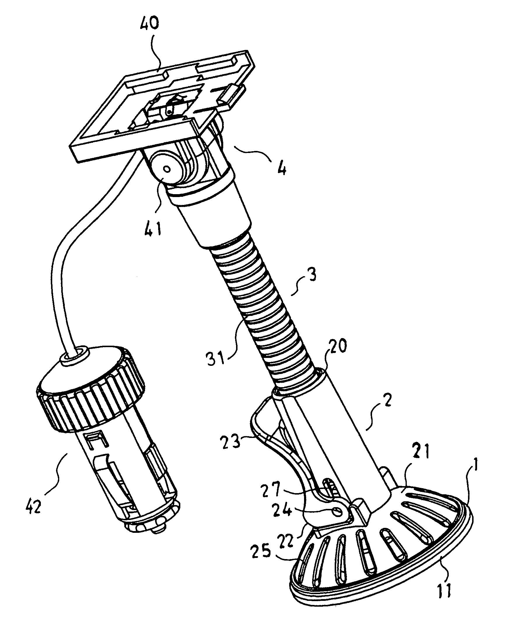
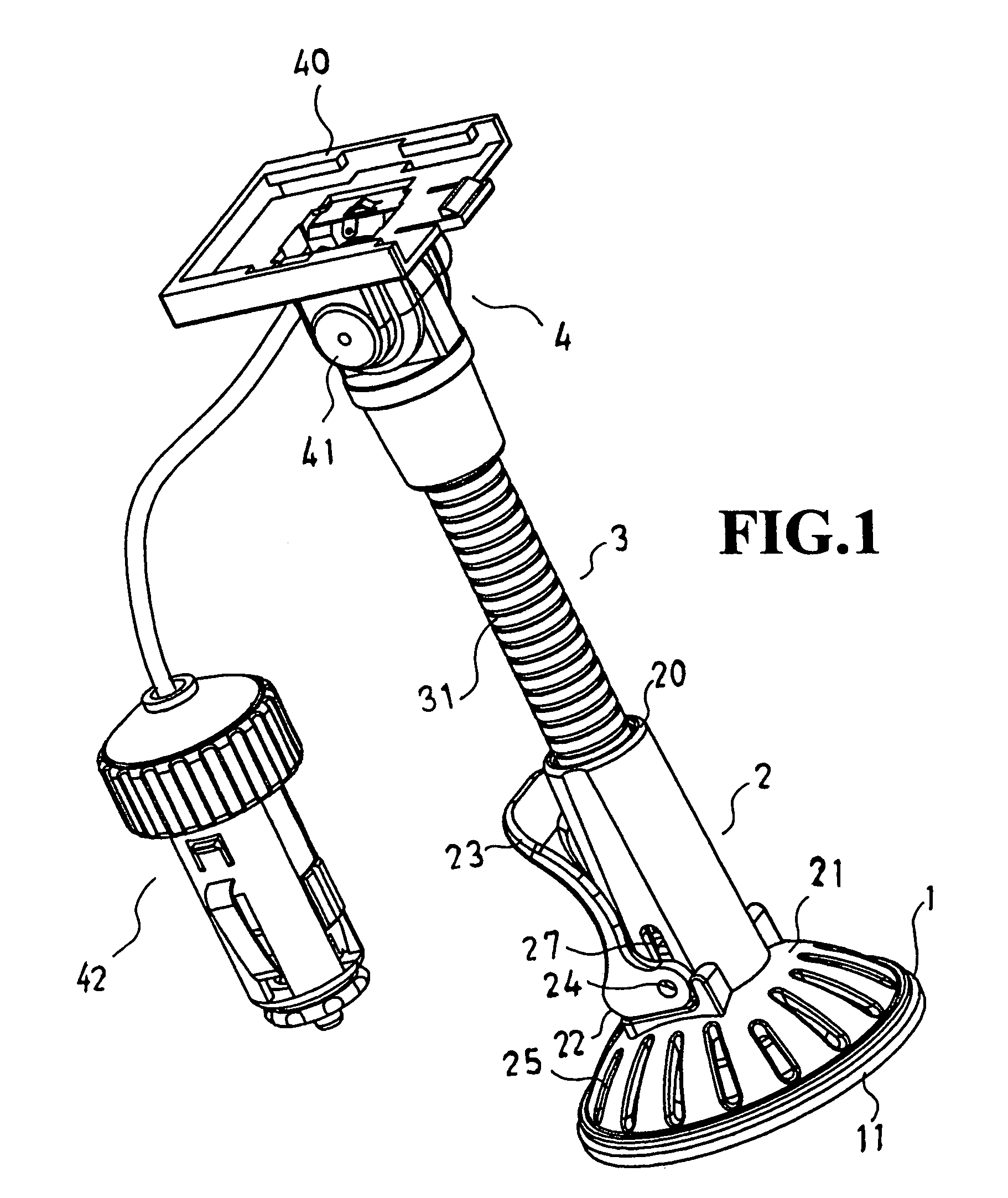
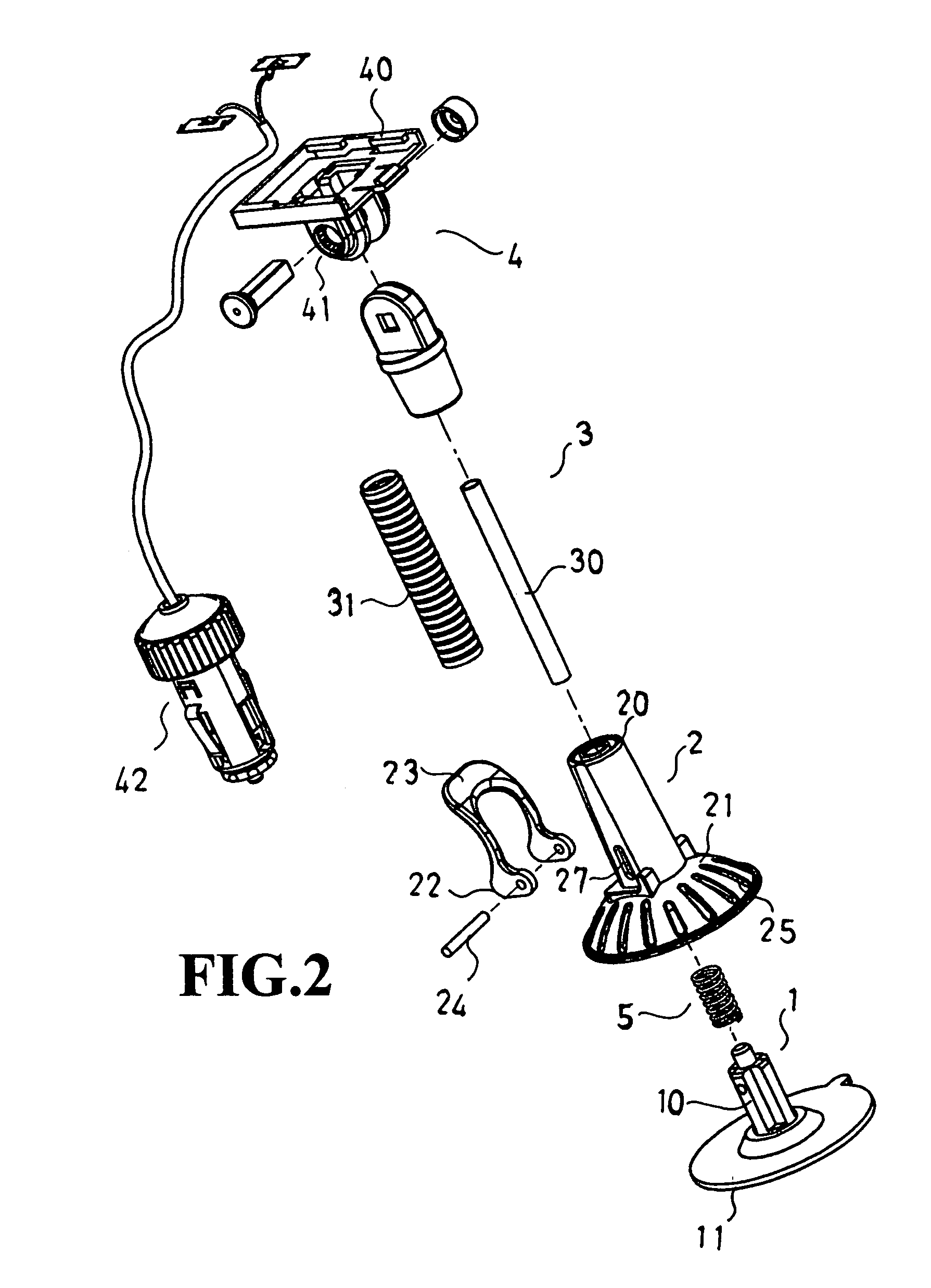
[0012]Please refer to the figures for the present invention. The present invention comprises a sucking disk body 1, a stand 2, a hanging pole 3 and a retaining base 4; wherein the sucking disk body 1 is a structure having a protruded cylindrical shaft 10 on top and a rubber sucking disk 11 on bottom; the stand 2 comprises a connecting sleeve 20 on top and a shell plate 21 on bottom; the shell plate 21 is slightly smaller than a sucking disk 11 of hte sucking disk body 1 and has a plurality of slots 25, a slot hole 26 disposed at center of the shell plate 21 and interconnected to a bar-shaped sliding groove 27 on a side; a spring 5 in the groove hole 26 props a protruded cylindrical shaft 10 of the sucking disk body 1, and the protruded...


PUM

PropertyMeasurementUnit
diameteraaaaaaaaaa
flexibleaaaaaaaaaa
flexibilityaaaaaaaaaa

Abstract

The present invention discloses an improved sucking disk type hanging pole which comprises a protruded shaft on top and a rubber sucking disk on bottom, a stand with a connecting sleeve on top and a shell plate on bottom, a flexible hanging pole and a retaining base for coupling a retained object; wherein the disk body of the stand is smaller than the rubber sucking disk; a through hole is disposed at the center and interconnected to a bar-shaped sliding groove; a spring disposed in the through hole props a protruded cylindrical shaft of the sucking disk body is; a pivotal axle rod of the protruded cylindrical shaft passes through a sliding groove and pivotally connects with a latch member, and the board latch member at its periphery comprises a cam edge for contacting and supporting a shell plate of the stand, so that the cam edge pushes the shell plate to move back and forth by turning the latch member in order to drive the protruded pole together by the spring to loosen the rubber sucking disk and allow the groove slot to deform the shell plate more easily and facilitate the slightly curved surface to have the sucking or loosening effects. Further, with the flexibility of the hanging pole, the present invention allows user to quickly adjust the direction and height of the retaining base and facilitate carrying a heavy load on a smooth fixing object such as a ceramic tile or glass.

Description

BACKGROUND OF THE INVENTION[0001]1. Field of the Invention[0002]The present invention relates to an improved sucking disk type hanging pole, more particularly to a sucking disk type hanging pole that enhances the convenience and reliability of the suction of the sucking disk. The present invention comprises a protruded cylindrical shaft at its top and a sucking disk body with a rubber sucking disk disposed at its bottom, a stand with a connecting sleeve on top and a shell plate on bottom, a flexible pole and a retaining base for coupling a retained object; wherein the disk body of the stand is slightly smaller than the sucking disk, and the sucking disk body has a groove; a through hole is disposed at the center of the bottom and interconnected to a bar-shaped sliding track at a lateral edge; a spring is propped in the protruded cylindrical shaft of the sucking disk body; a pivotal axle rod of the protruded cylindrical shaft passes through a sliding groove and pivotally connects wit...

Claims


Application Information

Patent Timeline
Patent Type & Authority Patents(United States)
IPC IPC(8): F16B47/00G11B23/03G11B33/00
CPCG11B33/00
Inventor TSAY, WEN-FENG
Owner TSAY WEN FENG
Learn More