Duct connection assemble between a branch duct and a main duct

a branch duct and duct connection technology, applied in the direction of pipe joints, pipeline expansion compensation, bends, etc., can solve the problems of water leakage at the connection between the saddle flange and the saddle flange, the adhesive agent may deteriorate and fall off the saddle flange, and the connection may be more prone to water leakage, so as to strengthen the engagement action

Inactive Publication Date: 2006-03-07
SANRITSU CORP
View PDF6 Cites 13 Cited by
  • Summary
  • Abstract
  • Description
  • Claims
  • Application Information

AI Technical Summary

Benefits of technology

[0021]According to other aspect of the invention, the hook portion has a stepped portion along a breadth direction to define a slantwise plane consecutively formed from a base plane. The slantwise plane is successively elevated toward a tip end of the hook portion. At the time of connecting the branch duct to the main duct, the hook portion elastically engages the slantwise plane with the inner edge around the upper opening so as to strengthen the engagement action.

Problems solved by technology

However, both the main duct and the saddle flange are formed by a hard synthetic resin material, and the saddle flange may slide against the main duct if they are shaken when subjected to an exterior force.
In addition, the adhesive agent may deteriorate to fall off the saddle flange.
This would result in the water leakage at the connection between the saddle flange and the main duct.
This is all the more prone to the water leakage because the adhesive agent is not per se suited to a water sealing action.

Method used


Image

  • Duct connection assemble between a branch duct and a main duct
  • Duct connection assemble between a branch duct and a main duct
  • Duct connection assemble between a branch duct and a main duct

Examples


first embodiment

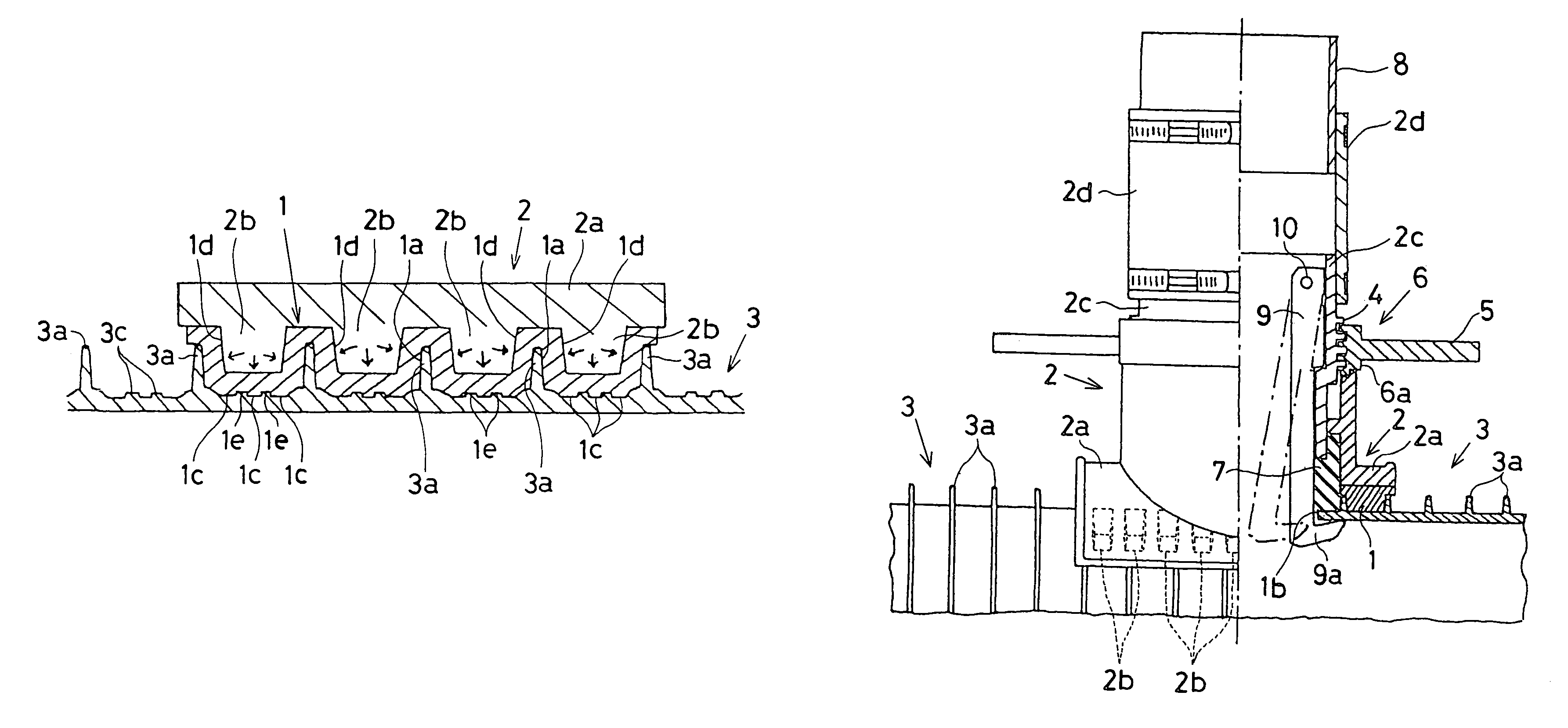
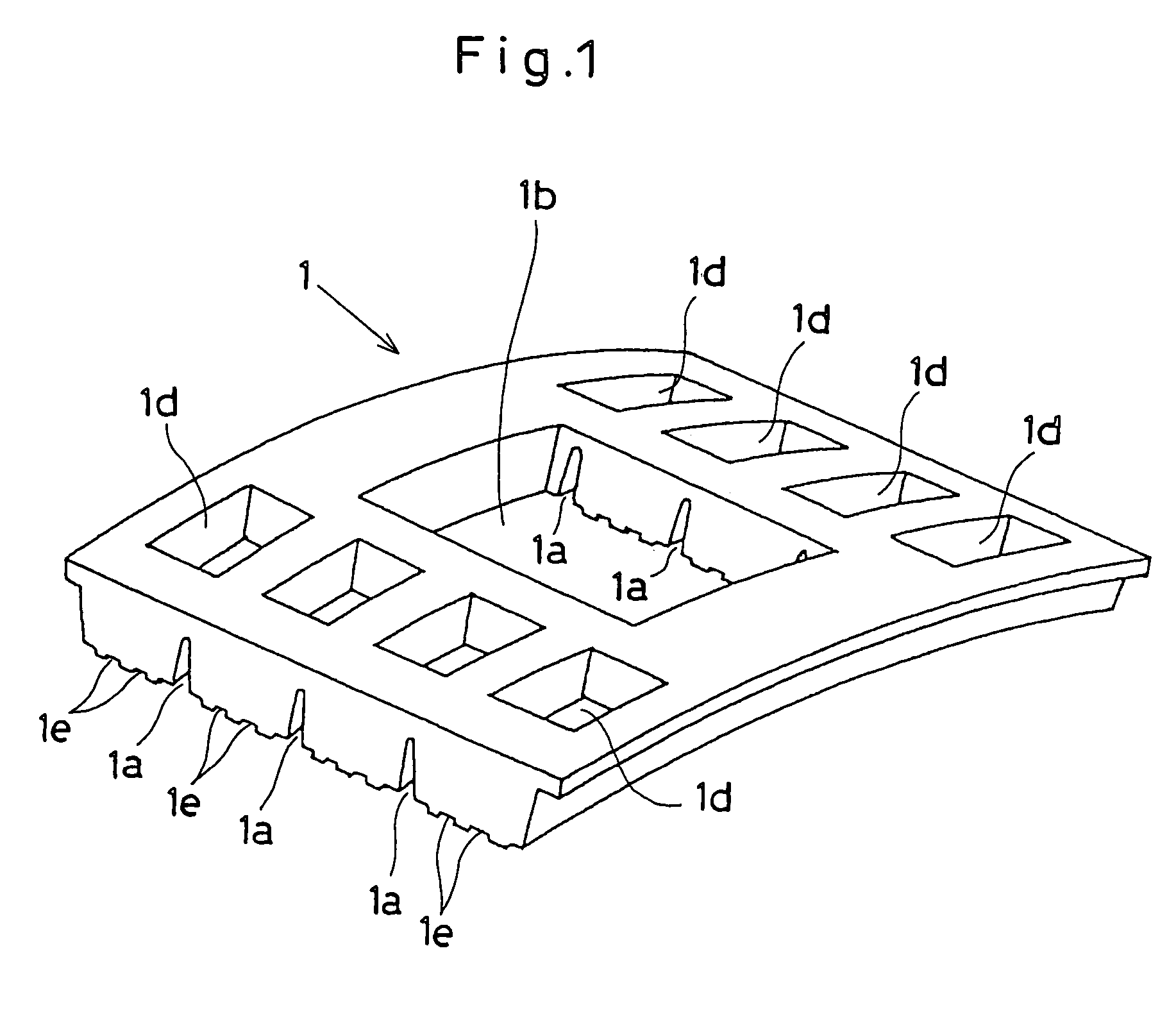
[0042]Referring to FIGS. 1 through 8 which show the invention, a rubber sealant 1 has a rectangular contour and warped to have a radius corresponding to that of a saddle flange 2a provided on a lower portion of a joint duct 2 as shown in FIGS. 1 and 2. An inner surface of the rubber sealant 1 has streaks of narrow and long grooves 1a (e.g., 2 to 3 mm in width) with regular intervals (e.g., 3 to 8 ridges) along a main ribbed duct 3 so as to fit the grooves 1a to ribs 3a provided on the main ribbed duct 3 upon connecting the saddle flange 2a to the main ribbed duct 3.

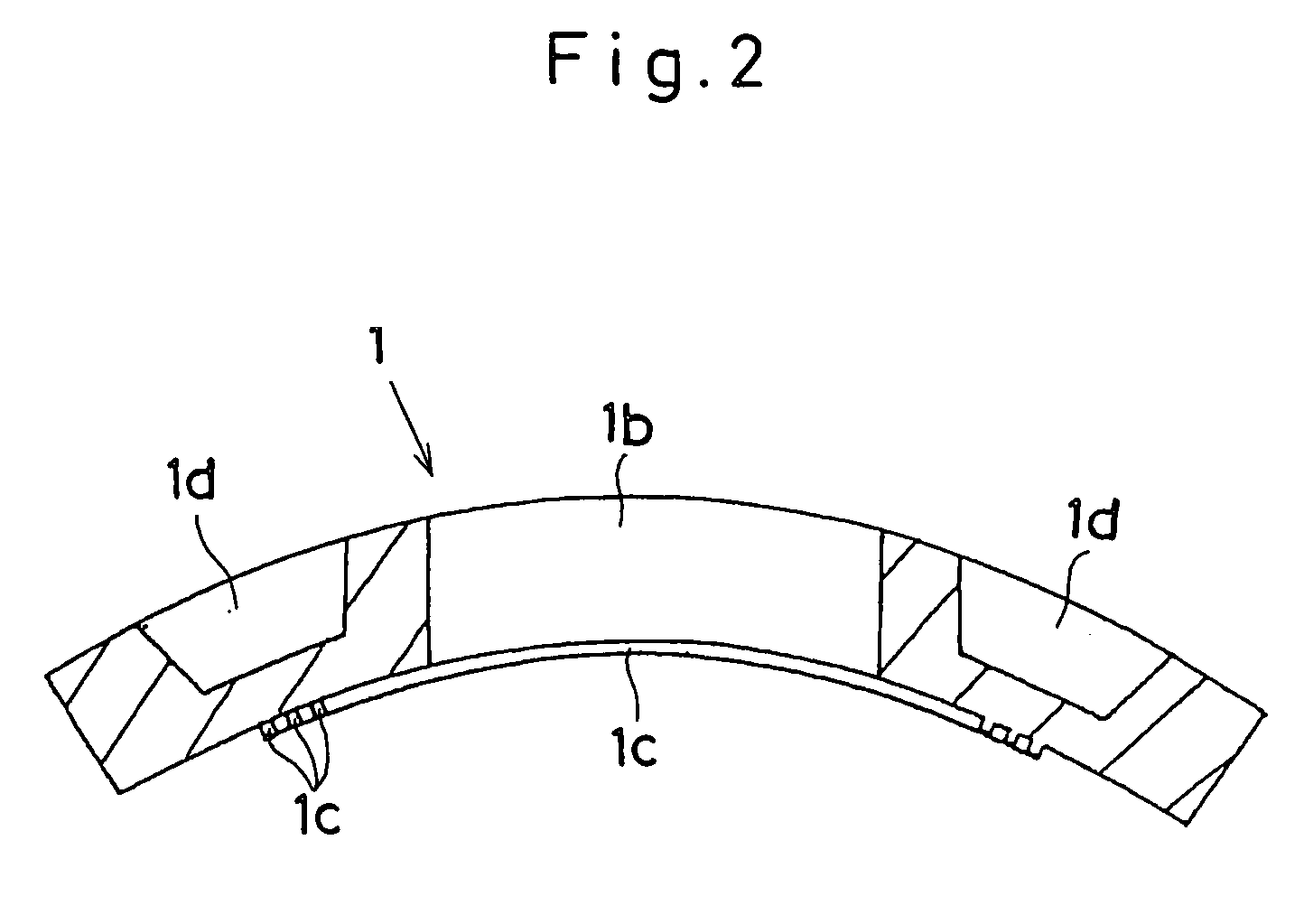
[0043]Provided with a central area of the rubber sealant 1, is a communication hole 1b in correspondence to an upper opening 3b provided on the main ribbed duct 3 as shown in FIG. 3. Around periphery of the communication hole 1b, concentrically provided are streaks of water sealing small projective rings 1c (e.g., three ridges each 1 to 3 mm in breadth and height). Opposite to the side in which the grooves 1a are provided...

second embodiment

[0053]FIGS. 12 through 15 show the invention in which the rubber sealant 1 is simply formed into an annular ring configuration to be attached to a ribless main duct 3A, and a pair of plastic stopper plates 20 is provided to position in diametrically opposed location.

[0054]The stopper plate 20 has substantially an L-shaped cross section so that the stopper plate 20 is located at a vertical recess 25 provided on an inner wall of the branch duct 2c. A hook portion 20a forms an acute angle (θ) (e. g., 80 degrees among an angular range of 020B of the stopper plate 20 as shown in FIG. 14. A pin 21 is provided on both upper elevational sides of the stopper plate 20 in correspondence to a groove22 formed on an upper open end of the branch duct 2c as a pin-and-groove combination. An L-shaped cavity 23 is provided on both sides of the vertical wall 20B of the stopper plate 20 in correspondence to a pin 24 formed on the inner wall of the branch duct 2c. The cavity 23 is paired at right and lef...

fourth embodiment

[0060]FIGS. 17 and 18 show the invention in which the hook portion 20a is slightly warped downward to define a curved plane. A basal portion of the curved plane forms either an acute angle (020B of the stopper plate 20.

[0061]FIG. 19 shows a fifth embodiment of the invention in which the hook portion 20a has a stepped portion 20f along a breadth direction to define a slantwise plane 20g consecutively formed from a base plane 20j. The slantwise plane 20g is successively elevated upward toward a tip end 20h of the hook portion 20a. At the time of connecting the branch duct 2c to the main duct 3A in the same manner as described at the second embodiment in FIG. 15, the hook portion 20a engages the slantwise plane 20g with the inner edge 3s around the upper opening 3b so as to strengthen the engagement action. In this instance, the base plane 20j forms either an acute angle (020B of the stopper plate 20.

[0062]It is to be noted that a pair of the L-shaped cavities 23 is not confined to two...


PUM


Abstract

A duct connection assemble, whereby upon connecting a saddle flange (2a) of the joint duct (8) to the main ribbed duct (3) through the communication hole (1b), the rubber sealant (1) is interposed between the saddle flange (2a) and a circumferential area of the communication hole (1b) so that protuberances (2b) uniformly press the rubber sealant (1) through the recesses (1d) to tightly engage the saddle flange (2a) against an outer surface of the main ribbed duct (3) through rib-fitting grooves (1a) and the water sealing small projective rings (1c). The joint duct (2) is brought into an elastical engagement with the main ribbed duct (3) to achieve a good water sealing action for an extended period of time.

Description

[0001]The invention is a continuation-in-part Application derived from U.S. patent application Ser. No. 10 / 297,400, now abandoned, filed Jun. 23, 2003, (International Application Filing Date: Jun. 8, 2000 (PCT / JP00 / 03742)).FIELD OF THE INVENTION[0002]The invention relates to a duct connection assemble provided between a branch duct and a main duct in an improved way to prevent a water leakage seeping through therebetween.BACKGROUND OF THE INVENTION[0003]This type of the connection assemble is disclosed by Laid-open Japanese Patent Application No. 7-119884 by way of illustration in which a duct assemble introduces domestic waste water to run into a main ribbed duct. The main duct has an array of ribs around its securement opening. A branch duct has a saddle flange which has undulating wavy portions. Upon putting the branch duct on the main duct for connection, the undulating wavy portions interfit into the ribs of the main duct. At this time, an adhesive agent may be applied to the c...

Claims


Application Information

Patent Timeline
Patent Type & Authority Patents(United States)
IPC IPC(8): F16L41/00F16L41/14
CPCF16L41/14Y10S285/903
Inventor OTSUGA, NORIOENAMI, HIROSHIOKAYAMA, KAZUMASA
Owner SANRITSU CORP
Why Eureka
Try Eureka