Supercharge Your Innovation With Domain-Expert AI Agents!

Hydrodynamic pivot bearing

a pivot bearing and hydrodynamic technology, applied in the direction of sliding contact bearings, mechanical energy handling, mechanical equipment, etc., can solve the problems of generating heat and noise, ball bearings creating debris, and failure of motors, so as to reduce the power consumption of spindle motors, save run current, and increase stability

Inactive Publication Date: 2006-03-07
MINEBEA CO LTD
View PDF15 Cites 2 Cited by
  • Summary
  • Abstract
  • Description
  • Claims
  • Application Information

AI Technical Summary

Benefits of technology

[0006]It is an object of the present invention to provide a spindle motor with a fluid dynamic pivot bearing which saves run-current and, therefore, reduces power consumption of the spindle motor. The present inventions combines the benefit of increased stability provided by hydrodynamic bearings with the benefit of low power consumption provided by pivot bearings.

Problems solved by technology

Ball bearings are wear parts and in time friction will cause failure of the motor.
In addition, ball bearings create debris in the form of dust or fine particles that can find their way into “clean” chambers housing the rotary magnetic disks which are driven by the motor.
The mechanical friction inherent in ball bearings also generates heat and noise, both of which are undesirable in a disk drive motor.

Method used


Image

  • Hydrodynamic pivot bearing
  • Hydrodynamic pivot bearing
  • Hydrodynamic pivot bearing

Examples


first embodiment

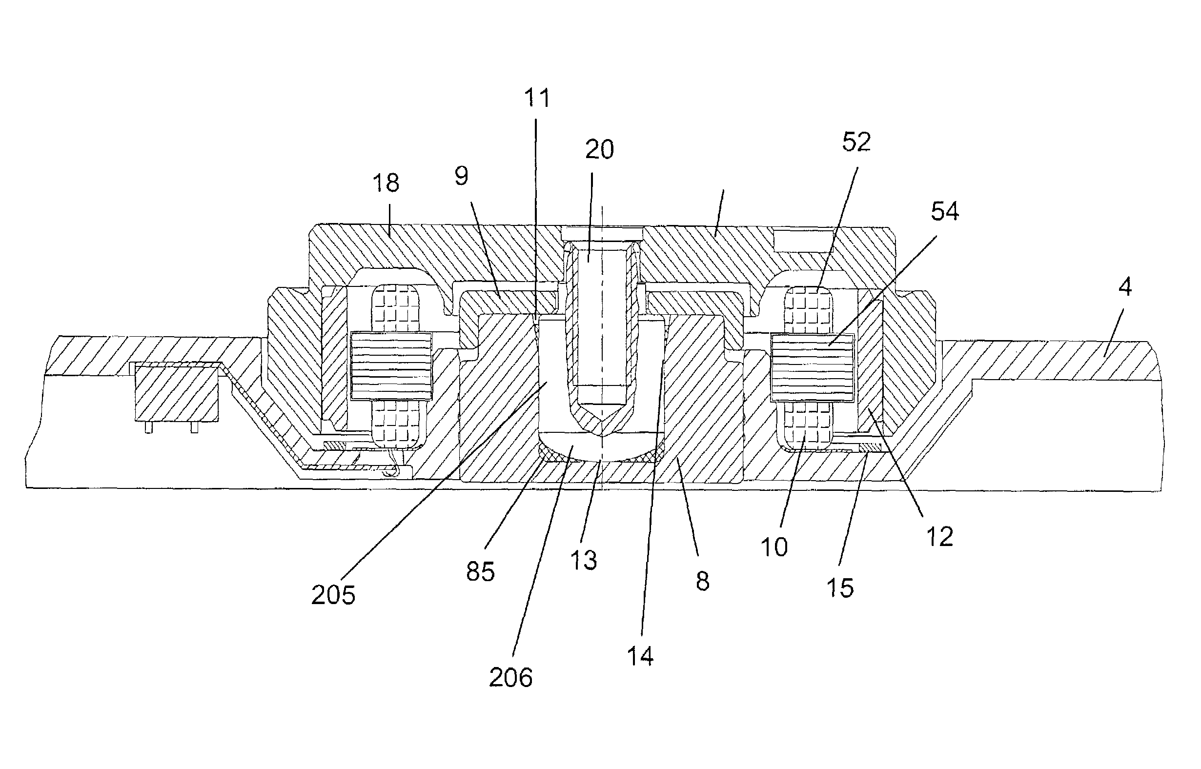
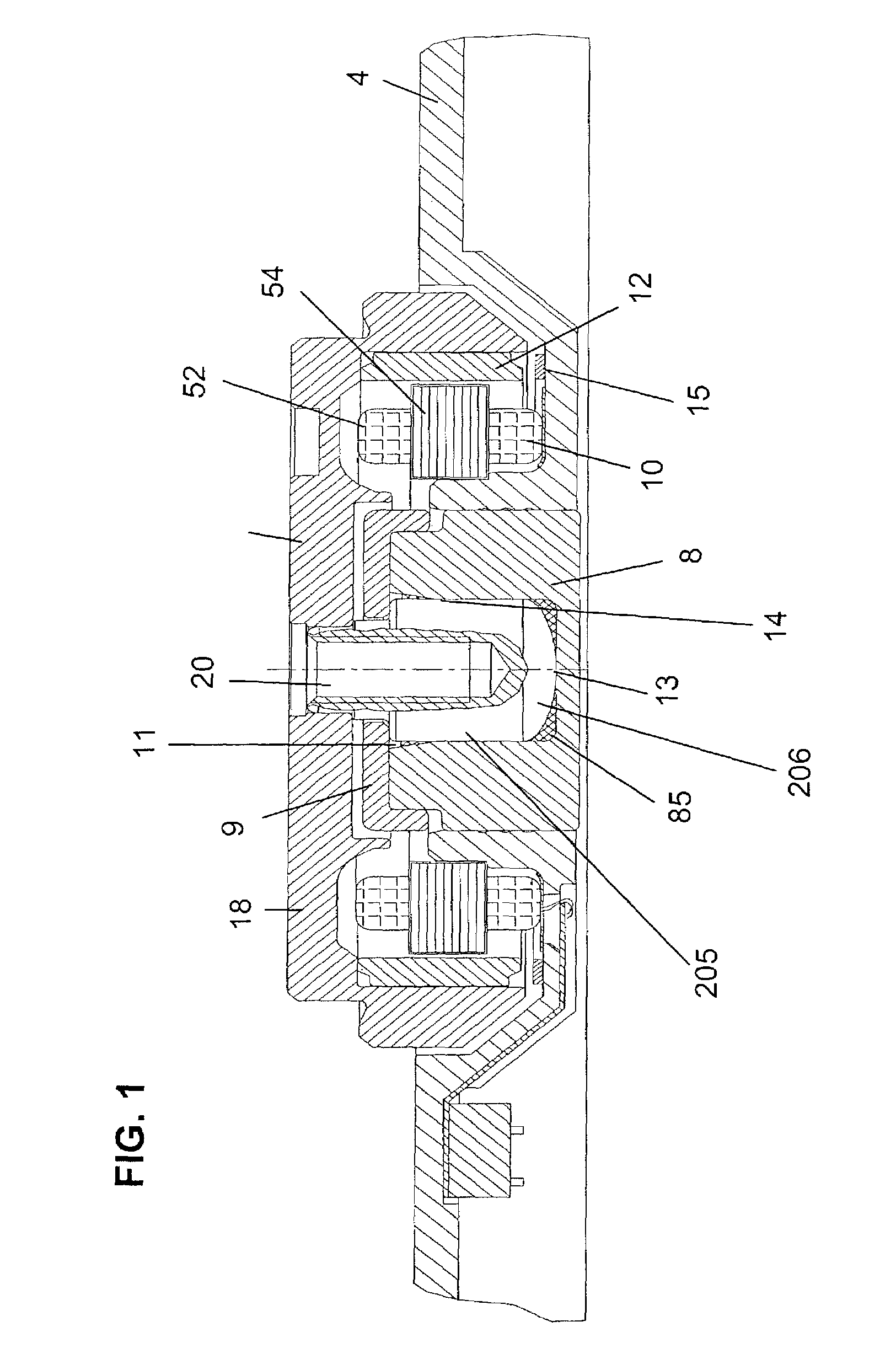
[0014]the present invention is shown in FIG. 1. A spindle motor includes a stator 10 and a rotor 6 that is arranged for rotation relative to stator 10.

[0015]The rotor 6 comprises a rotor hub 18 and a tubular shaft 20 fixed coaxially to the rotor hub 18. A rotor magnet 12 is bonded to the inner side of a circumferential wall of the rotor hub 18. The outer side of the circumferential wall of the rotor hub 18 is shaped to hold a magnetic disk (not shown).

[0016]Stator 10 comprises bracket 4 which is to be mounted on a disk drive device (not shown); sleeve 8; core 52, which is fixedly mounted to bracket 4, and coils 54 wound on the core 52. Coils 54 are radially spaced by a small gap from and arranged opposite to the rotor magnet 12.

[0017]Sleeve 8 is a tubular member into which is formed a cylindrical hole 85. With the exception of its upper most portion, cylindrical hole 85 has a constant radius A. The uppermost portion of cylindrical hole 85 has a slightly increased radius to provide f...

second embodiment

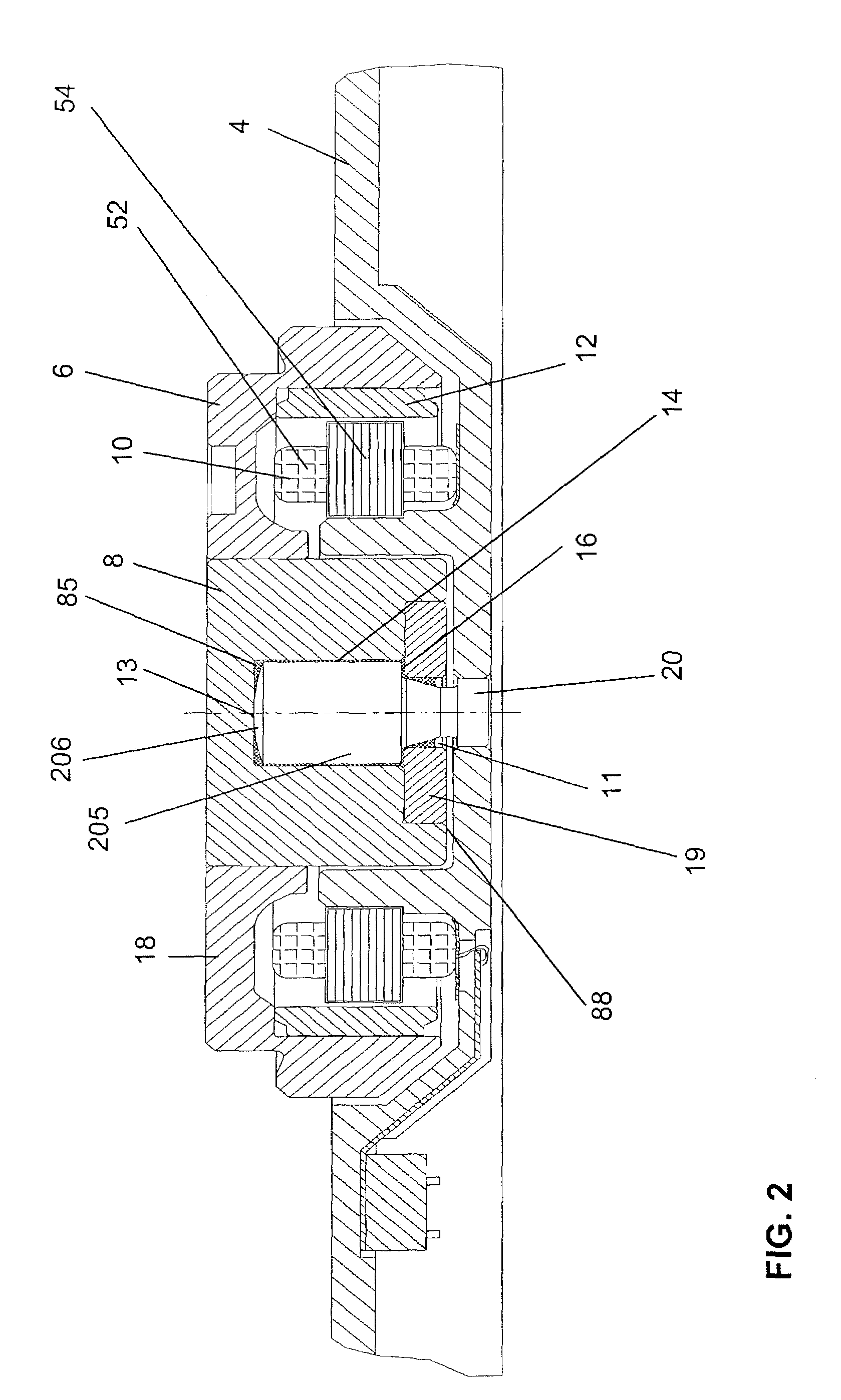
[0021]the present invention is shown in FIG. 2 and in FIG. 3. The rotating shaft version of this spindle motor is shown in FIG. 3. A spindle motor includes a stator 10 and a rotor 6 that is arranged for rotation relative to stator 10.

[0022]The rotor 6 comprises a rotor hub 18 and a tubular shaft 20 fixed coaxially to the rotor hub 18. A rotor magnet 12 is bonded to the inner side of a circumferential wall of the rotor hub 18. The outer side of the circumferential wall of the rotor hub 18 is shaped to hold a magnetic disk (not shown).

[0023]Stator 10 comprises bracket 4 which is to be mounted on a disk drive device (not shown); sleeve 8; core 52, which is fixedly mounted to bracket 4, and coils 54 wound on the core 52. Coils 54 are radially spaced by a small gap from and arranged opposite to rotor magnet 12.

[0024]Sleeve 8 is a tubular member into which is formed a cylindrical hole 85. Cylindrical hole 85 has a constant radius A. Directly above cylindrical hole 85 and coaxial with cyli...

third embodiment

[0033]the present invention is shown in FIG. 4 and in FIG. 5. The rotating shaft version of this spindle motor is shown in FIG. 4. It includes a stator 10 and a rotor 6 that is arranged for rotation relative to stator 10.

[0034]Rotor 6 comprises a rotor hub 18 and a tubular shaft 20 fixed coaxially to the rotor hub 18. A rotor magnet 12 is bonded to the inner side of a circumferential wall of the rotor hub 18. The outer side of the circumferential wall of the rotor hub 18 is shaped to hold a magnetic disk (not shown).

[0035]Stator 10 comprises bracket 4, which is to be mounted on a disk drive device (not shown); sleeve 8; core 52, which is fixedly mounted to bracket 4; and coils 54 wound on the core 52. Coils 54 are radially spaced by a small gap from and arranged opposite to the rotor magnet 12.

[0036]Sleeve 8 is a tubular member into which is formed a cylindrical hole 85. Cylindrical hole 85 has a constant radius A. Directly above cylindrical hole 85 and coaxial with cylindrical hole...


PUM


Abstract

The present invention provides a bearing comprised of a hydrodynamic bearing and a pivot bearing, which can be used with a spindle motor. It also provides a spindle motor utilizing a hydrodynamic bearing and a pivot bearing.

Description

CROSS-REFERENCE TO RELATED APPLICATIONS[0001]This application claims priority from Fed. Rep. Of Germany Patent Application Nos. DE10232933.8, filed on Jul. 19, 2002; DE10237848.7, filed on Aug. 19, 2002; and DE10240634, filed on Sep. 2, 2002; and from U.S. Provisional Patent Application Ser. No. 60 / 363,784, filed on Mar. 12, 2002.BACKGROUND OF THE INVENTION[0002]The following invention relates to electronic spindle motors of the type used in disk drives and in particular relates to improvements in fluid bearings for such motors.[0003]Disc drive systems have been used in computers and other electronic devices for many years for storage of digital information. Information is recorded on concentric memory tracks of a magnetic disc medium, the actual information being stored in the form of magnetic transitions within the medium. The discs themselves are rotatably mounted on a spindle, the information being accessed by means of transducers located on a pivoting arm which moves radially o...

Claims


Application Information

Patent Timeline
Patent Type & Authority Patents(United States)
IPC IPC(8): F16C32/06F16C33/74H02K5/167H02K7/08
CPCF16C17/10F16C33/107F16C33/74H02K7/086H02K7/085F16C2370/12H02K7/09
Inventor KULL, ANDREASWINTERHALTER, OLAFHOFFMANN, JOERGHAFEN, MARTIN
Owner MINEBEA CO LTD
Features
  • R&D
  • Intellectual Property
  • Life Sciences
  • Materials
  • Tech Scout
  • Unparalleled Data Quality
  • Higher Quality Content
  • 60% Fewer Hallucinations
Learn More