Coaxial cable connector with deformable compression sleeve

a compression sleeve and coaxial cable technology, applied in the direction of electrical apparatus, connection, coupling device connection, etc., can solve the problems of connector loosening, connector loosening, connector loosening, etc., and achieve the effect of convenient alignmen

Active Publication Date: 2006-03-07
HOLLAND ELECTRONICS
View PDF8 Cites 68 Cited by
  • Summary
  • Abstract
  • Description
  • Claims
  • Application Information

AI Technical Summary

Benefits of technology

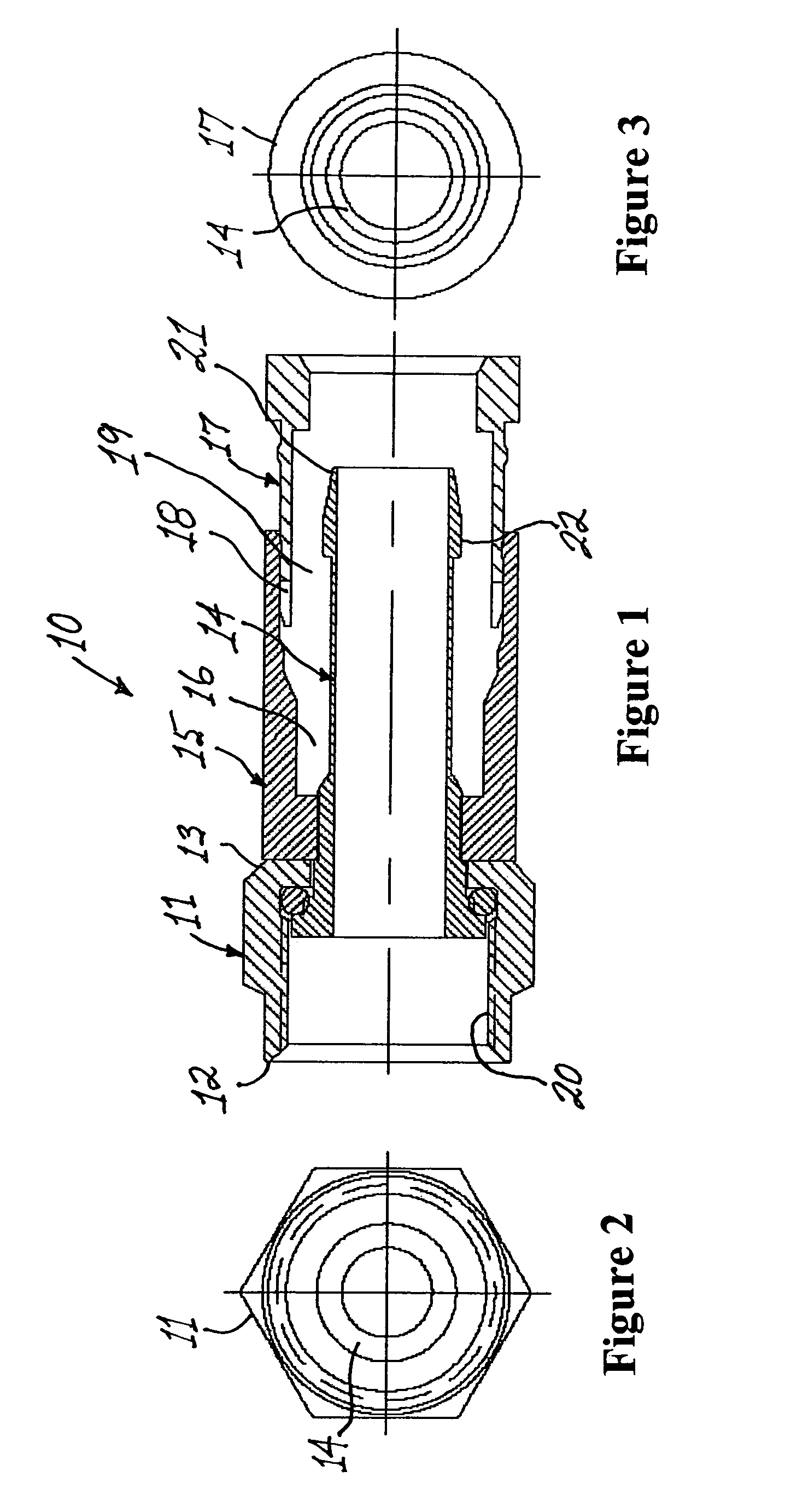
[0011]In a first embodiment, the removable compression sleeve is a substantially cylindrical tubular member having a deformable leading end, a trailing end and a third axial conduit coextensive with the length thereof, the third axial conduit being dimensioned to enable the snug passage of a coaxial cable therethrough. The deformable leading end of the removable compression sleeve, which may be either tubular or slotted, is deformable inwardly. The outer surface of the compression sleeve has first detent means preferably comprising a first annular groove thereon adjacent the leading end thereof. The tubular body portion preferably includes a first annular ridge projecting radially inwardly from the wall of the second axial conduit. When the leading end of the compression sleeve is advanced forwardly through the trailing end of the second axial conduit in the tubular body portion, the first annular ridge within the second axial conduit of the tubular body portion releasably engages the first annular groove on the compression sleeve to form a compressible coaxial cable connector assembly having “semi integral” construction in the sense that although the compression sleeve is removable, it is loosely held within the second axial conduit by detent means unless intentionally removed such as in the event it is necessary to replace the compression sleeve with a compression sleeve having an axial conduit with a different inner diameter. The term “detachable”, as used herein to describe a compression sleeve, means that the compression sleeve may be facilely detached and removed from the connector and reattached thereto without damaging either the compression sleeve or the connector body.
[0015]In practice, when inserting the prepared end of a coaxial cable into a coaxial cable connector, the cable must be inserted such that the barbed trailing end of the ferrule in the connector separates the layer of braided shielding and overlying jacket of the cable from the underlying dielectric layer and interposes itself therebetween. In one embodiment of the present invention, the barb is disposed forward of the trailing end of the ferrule. This modification enables the installer to more easily align and insert the prepared end of a coaxial cable into the connector's axial conduit such that the ferrule is disposed between the braid and the underlying dielectric layer of the cable prior to advancement over the larger diameter barb.

Problems solved by technology

While the innovative plethora of prior art connectors, some of which are disclosed above, provide improved moisture sealing and / or RF leakage characteristics, all have inherent limitations.
If the installer fails to completely compress the connector, especially in the final 20 percent of the compressive range, the connector may come loose.
In addition, if the cable is not fully inserted into the conduit, the connector may come loose and / or the electrical connection may fail.
If the trailing end of the ferrule is recessed too deeply within the trailing end of a connector, it may be difficult to achieve proper alignment in order to accomplish the intended function.

Method used


Image

  • Coaxial cable connector with deformable compression sleeve
  • Coaxial cable connector with deformable compression sleeve
  • Coaxial cable connector with deformable compression sleeve

Examples


Embodiment Construction

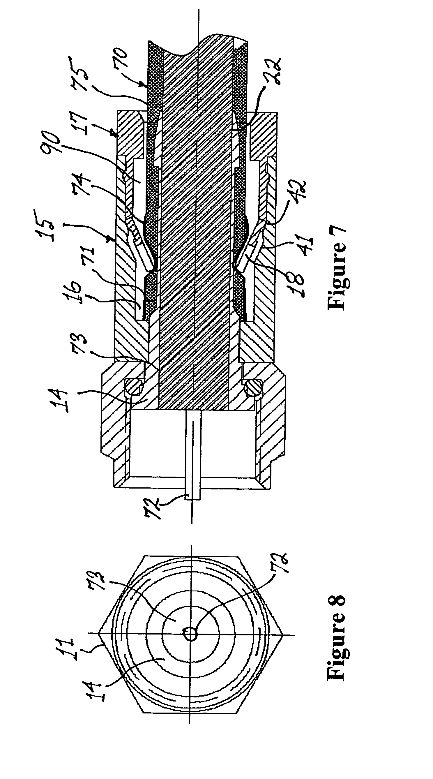
[0040]Prior to attaching a coaxial cable to a male connector, the end of the cable that will be receiving the connector must first be prepared. It will be understood by the artisan that the preparation of the end of the cable will be in accordance with the type of male coaxial cable connector that the cable 70 (FIG. 7) will be attached (i.e., F-type, BNC, RCA, etc.). In order to prepare the end of a coaxial cable to receive a male connector, a cutting tool is used by an installer to expose a portion of the central conductor 72, a length of the dielectric core 73 and a conductive (grounding) braid 74, as shown in FIG. 7. Again, the respective lengths of each of the elements comprising the coaxial cable 70 that are exposed by the cutting tool will depend on the particular type of male connector to be attached thereto and are in accordance with industry standards. Following exposure of the conductive braid 74, the exposed portion of conductive braid is flared and folded back to overlie...


PUM


Abstract

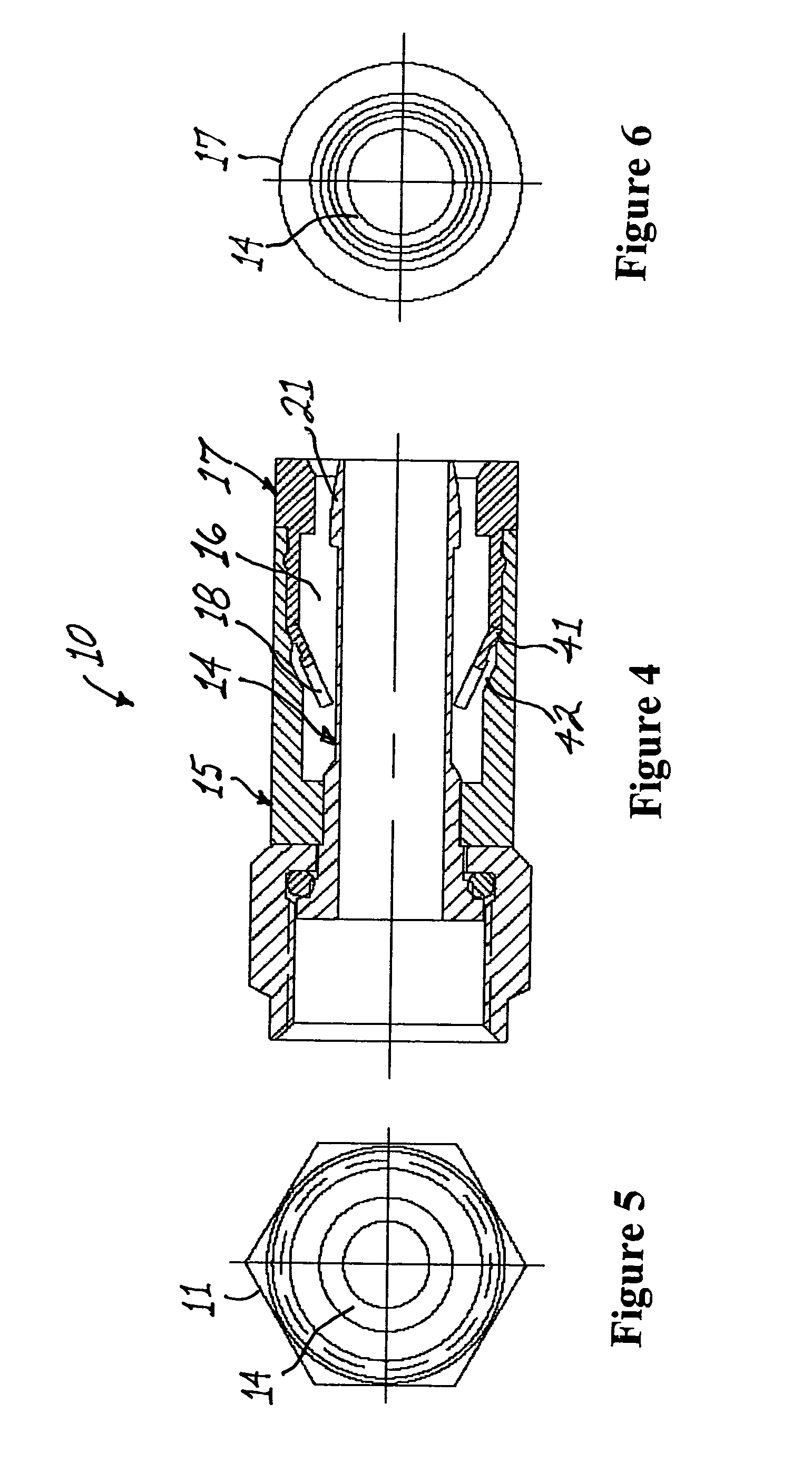
A male compression-type coaxial cable connector having a compression sleeve slidingly disposed within an axial conduit within a connector body. The prepared end of the coaxial cable is inserted through the compression sleeve and advanced into the connector body. Subsequent advancement of the compression sleeve within the axial conduit, with the assistance of a compression tool, forces the deformable leading end of the compression sleeve radially inward to compress the cable jacket and braid thereby providing secure attachment of the connector to the cable. In a first embodiment, the compression sleeve is removable and can be replaced with another compression sleeve having a different inner diameter to accommodate a variety of coaxial cables. In a second embodiment, the compression sleeve is permanently attached to the connector. Advancement of the compression sleeve forces a separate compression ring disposed within the conduit forwardly, the compression ring deforming inwardly during advancement to affix the cable to the connector. In a third embodiment, the barb, which is disposed on the trailing end of prior art shanks, is disposed forward of the trailing end of the shank.

Description

[0001]This application claims the benefit of U.S. Provisional Application No. 60 / 572,173, filed May 18, 2004.BACKGROUND OF THE INVENTION[0002]1. Field of the Invention[0003]The present invention relates to male coaxial cable connectors operable for electrically connecting a coaxial cable to a mating female port, and, more particularly, in a first embodiment to a male coaxial cable connector having a compression sleeve with a deformable leading end slidably disposed within an axial conduit of a body portion of the connector. In a second embodiment, a separate compression ring is disposed within the axial conduit forward of the compression sleeve.[0004]2. Prior Art[0005]Connectors adapted to form a secure, electrically conductive connection between a coaxial cable and a threaded female port have are well known in the art. Such prior art connectors are discussed, for example, in U.S. Pat. No. 6,217,383 to Holland et al., U.S. Pat. Nos. 6,676,446, 6,153,830 and U.S. Pat. No. 6,558,194 t...

Claims


Application Information

Patent Timeline
Patent Type & Authority Patents(United States)
IPC IPC(8): H01R9/05H01R13/58
CPCH01R9/0518H01R13/5837H01R13/5808
Inventor HOLLAND, MICHAEL
Owner HOLLAND ELECTRONICS
Why Eureka
Try Eureka