Inter-vertebral disc prosthesis for rachis through anterior surgery thereof

a technology for intervertebral discs and prostheses, applied in the field of disc prostheses for the rachis, can solve the problems of loss of mobility and damping, premature ageing of these natural discs,

Inactive Publication Date: 2006-03-07
ORTHOPLEX
View PDF41 Cites 89 Cited by
  • Summary
  • Abstract
  • Description
  • Claims
  • Application Information

AI Technical Summary

Benefits of technology

[0032]Specifically, one of said upper and lower members defines a U-shaped recess with the other one of said upper and lower members defining an extension adapted to be slidably received in said recess such that said upper and lower members are slidably displaceable along direction s

Problems solved by technology

When a cervical disc is anteriorly removed (e.g. using the Smith-Robinson surgical technique) from between two adjacent vertebrae, for instance to liberate roots and/or medulla which are compressed by a degenerated disc or to remove a damaged disc, it is known to fuse both these vertebrae together (i.e. osteosynthesis by way of an anterior cervical plate) to provide stability t

Method used


Image

  • Inter-vertebral disc prosthesis for rachis through anterior surgery thereof
  • Inter-vertebral disc prosthesis for rachis through anterior surgery thereof
  • Inter-vertebral disc prosthesis for rachis through anterior surgery thereof

Examples


second embodiment

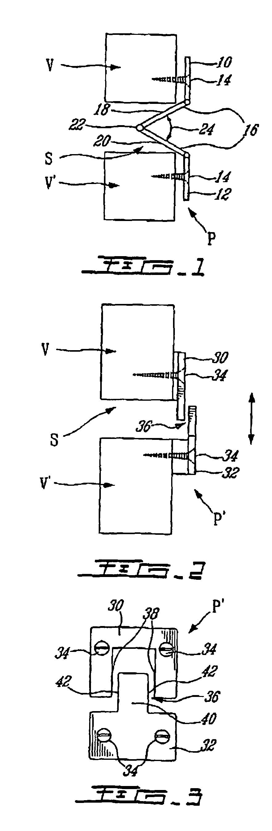
[0052]In FIGS. 2 and 3, there is shown a disc prosthesis P′ also in accordance with the present invention and which has a cigar-cutter configuration, being located completely anteriorly of the upper and lower vertebrae V and V such as to provide for translational displacements along an axial plane between the vertebrae V and V (as opposed to the pivoting movement of the first disc prosthesis P of FIGS. 1 and 1A).

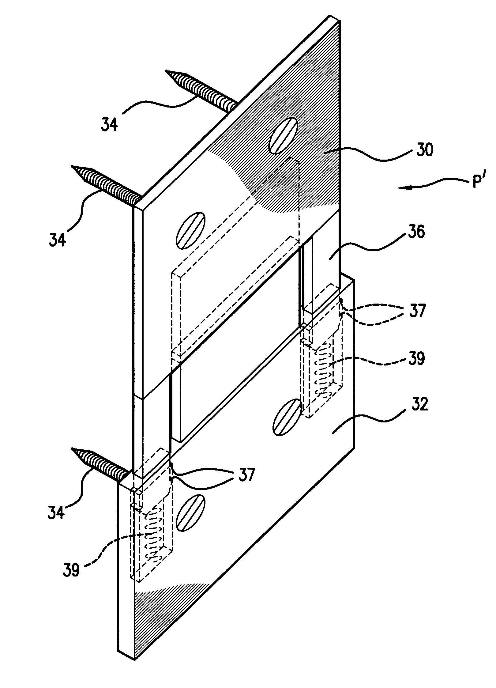
[0053]The second prosthesis P (see FIGS. 2, 2A and 3) comprises upper and lower anchoring plates 30 and 32, respectively, which are adapted to be secured with screws 34 to anterior faces of the adjacent upper and lower vertebrae V and V′. This second prosthesis P′ may also be used on the various vertebrae of the rachis, including advantageously on the cervical rachis. The prosthesis P′ also includes a joint 36 connecting both plates 30 and 32 to link both vertebrae V and V′ in a stable manner and further providing damping characteristics to the prosthesis P′ and relative mov...

third embodiment

[0058]In FIGS. 4 to 6 which show a third embodiment also in accordance with the present invention, a further disc prosthesis P″ is illustrated and is, in fact, a one-piece tissue jacket 100 defining a posterior bi-concave constraining chamber 102 adapted to receive therein a hydrogel 104 that acts as a damper, with anterior frontally extending upper and lower extensions 106 and 108, respectively, adapted to be anchored to the anterior faces of the facing upper and lower vertebrae V and V′ with screws 112 that extend through reinforced eyelets 110.

[0059]More particularly, the bi-concave hydrogel 104 of the joint of disc prosthesis pH conforms to or mimics the natural shape of a cervical disc (16, 18 or 20 mm depth.times.6, 8 or 10 mm height) and is surrounded or coated with the deformable constraining jacket 100 located in an intra-spinal inter-somatic space. The pair of frontal, extra-spinal and pre-somatic, upper and lower extensions 106 and 108 extend respectively from the antero-...


PUM

PropertyMeasurementUnit
Sizeaaaaaaaaaa

Abstract

A disc prosthesis for use on a pair of adjacent vertebrae comprises upper and lower plates adapted to be mounted respectively to adjacent upper and lower vertebrae, typically using screws that extend through holes defined in the upper and lower plates and into the upper and lower vertebrae; a joint mechanism linking the upper and lower plates; and a damping system. The joint mechanism and the damping system are adapted to allow for biased relative movements between the upper and lower vertebrae.

Description

[0001]This application claims the benefit of U.S. Provisional Application No. 60 / 206,810, filed on May 25, 2000, and U.S. Provisional Application No. 60 / 264,309, filed on Jan. 29, 2001.BACKGROUND OF THE INVENTION[0002](a) Field of the Invention[0003]The present invention relates to disc prostheses for the rachis and, more particularly, to disc prostheses installable through anterior surgery.[0004](b) Description of Prior Art[0005]When a cervical disc is anteriorly removed (e.g. using the Smith-Robinson surgical technique) from between two adjacent vertebrae, for instance to liberate roots and / or medulla which are compressed by a degenerated disc or to remove a damaged disc, it is known to fuse both these vertebrae together (i.e. osteosynthesis by way of an anterior cervical plate) to provide stability to the rachis although this results in loss of mobility and damping. This rigidification (on one or more successive discs) induces greater stresses to the natural discs located adjacen...

Claims


Application Information

Patent Timeline
IPC IPC(8): A61F2/44A61B17/80A61B17/56A61B17/70A61FA61F2/00A61F2/30
CPCA61B17/7059A61F2/441A61F2/442A61F2/4425A61F2230/0054A61B17/8009A61F2002/30172A61F2002/30176A61F2002/30372A61F2002/3038A61F2002/30471A61F2002/30563A61F2002/30566A61F2002/30571A61F2002/30578A61F2002/30624A61F2002/30777A61F2002/30787A61F2002/30975A61F2220/0033A61F2220/0091A61F2230/0052A61B17/8004A61F2002/30331
Inventor SEVRAIN, LIONEL C.
Owner ORTHOPLEX
Why Eureka
Try Eureka