Mounting frame unit for attaching working implements to a tractor body

Active Publication Date: 2006-03-14
KUBOTA LTD
View PDF4 Cites 8 Cited by
  • Summary
  • Abstract
  • Description
  • Claims
  • Application Information

AI Technical Summary

Benefits of technology

[0006]Having regard to the disadvantage of the prior art noted above, the object of this invention is to provide a mounting frame unit of simple constru

Problems solved by technology

Such a conventional TLB has a drawback of requiring many components for the rear portions of the mounting frame to be mounted on the rear axle cases.
This construction is said to give difficulty to the

Method used


Image

  • Mounting frame unit for attaching working implements to a tractor body
  • Mounting frame unit for attaching working implements to a tractor body
  • Mounting frame unit for attaching working implements to a tractor body

Examples


Example

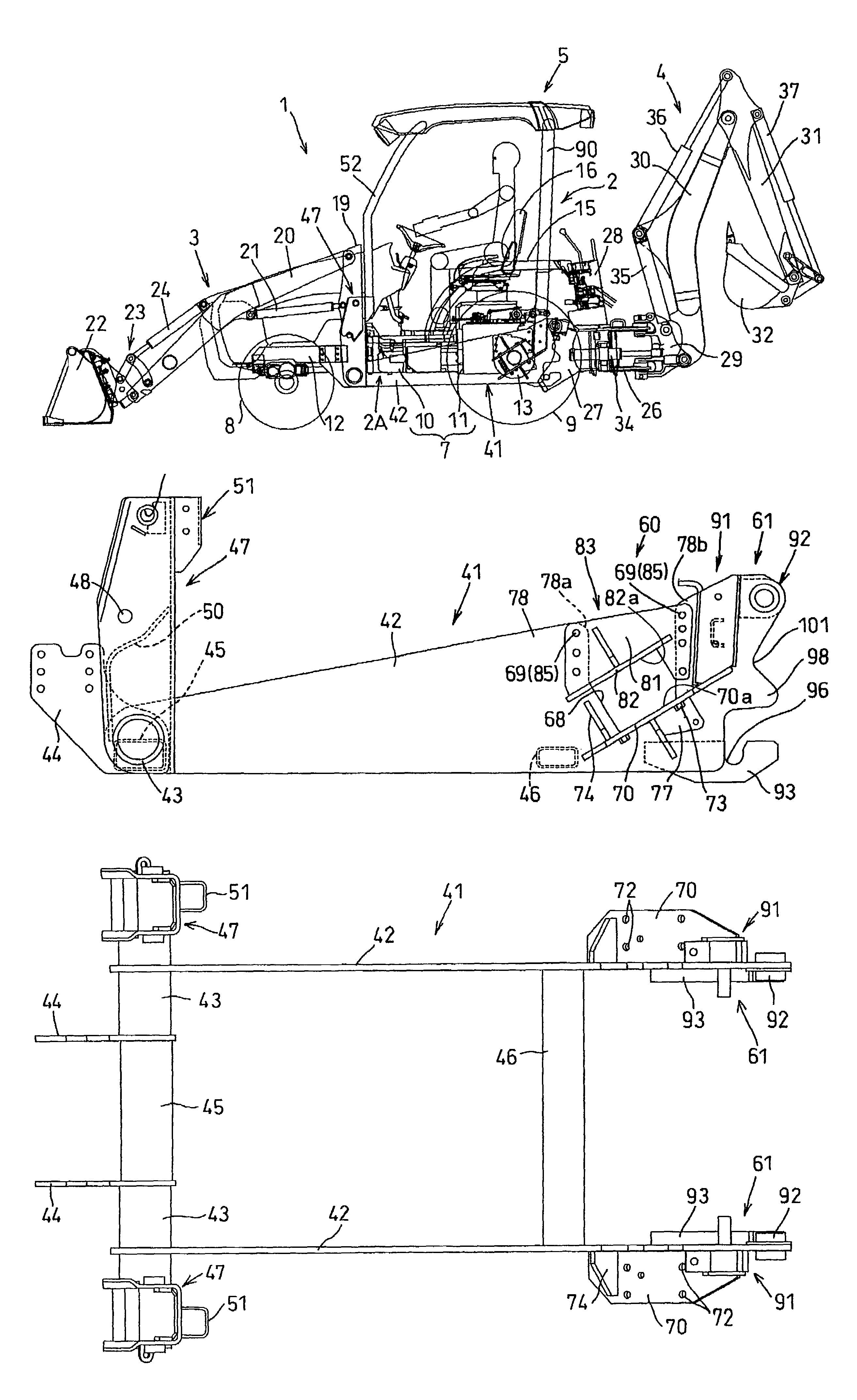
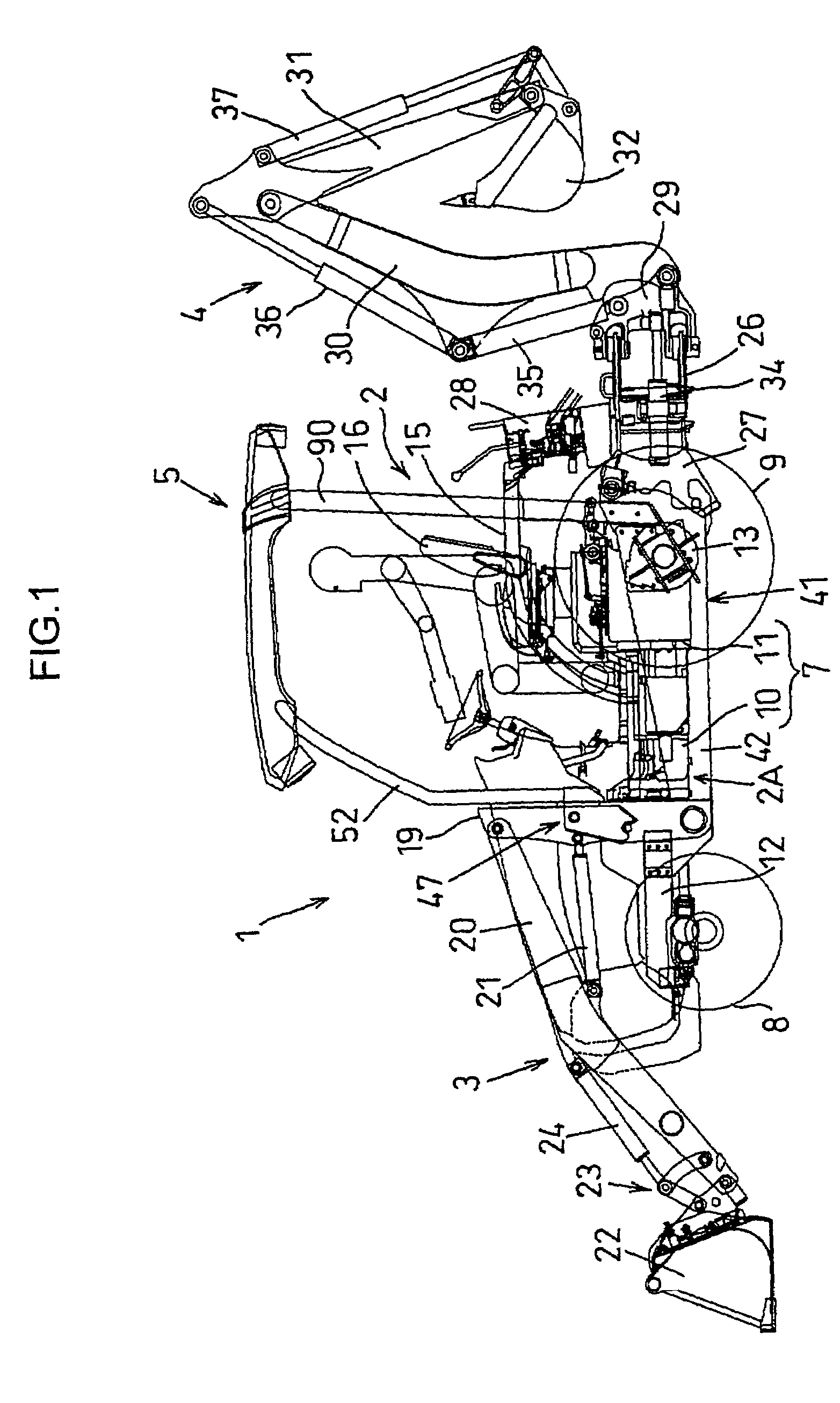
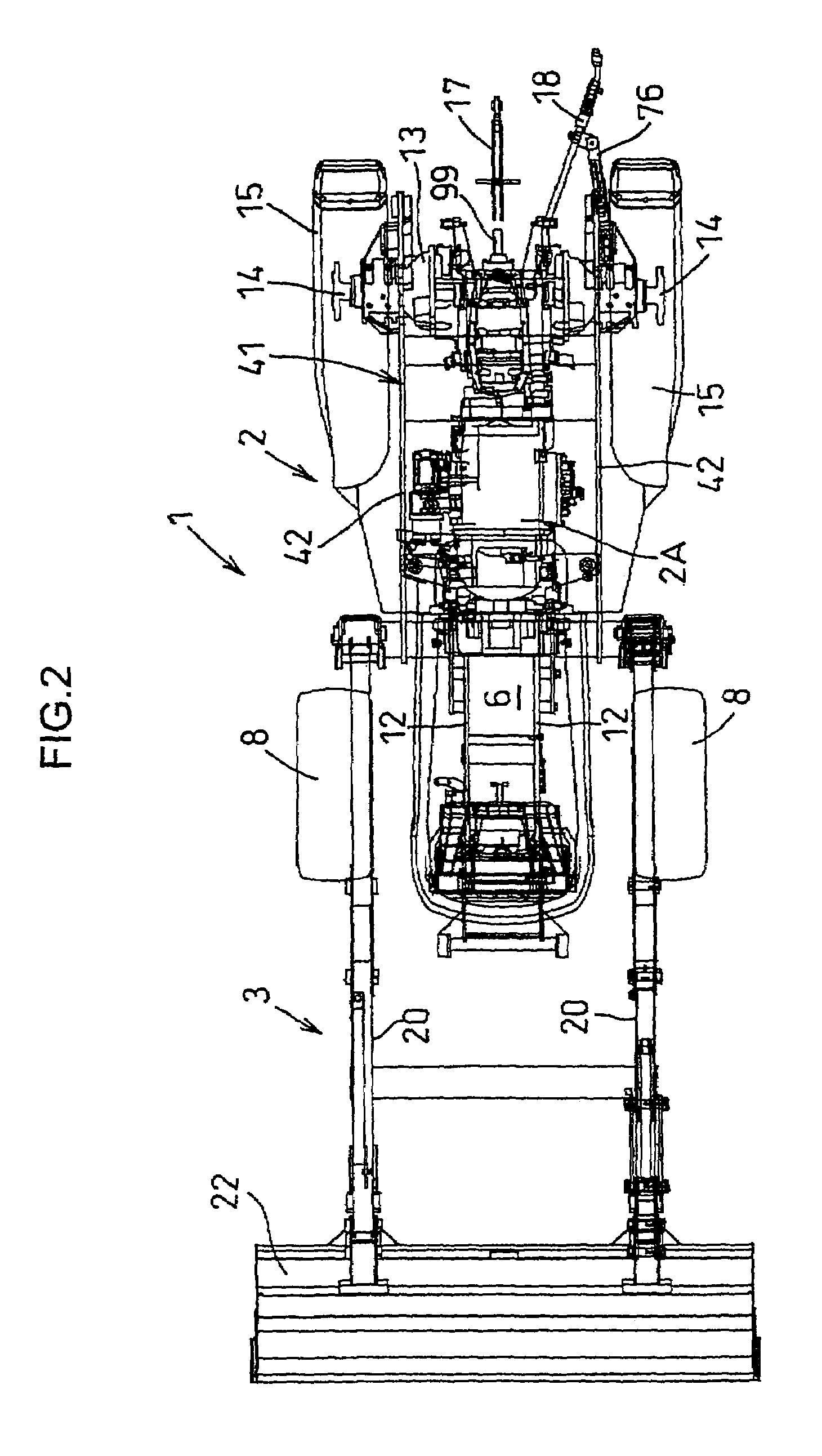
[0030]In FIGS. 1 through 3, numeral 1 denotes a working vehicle called a TLB including a tractor 2 with a front loader 3 detachably attached to the front thereof, and a backhoe 4 detachably attached to the rear of the tractor 2.

[0031]The front loader 3 has a braceless structure.

[0032]The TLB 1 includes a FOPS / ROPS 5 with a four-post type ROPS having a FOPS function.

[0033]The tractor 2 includes a three-point link mechanism having a top link 17 and a pair of right and left lower links 18 attached to the rear of a tractor body 2A. Through this three-point link mechanism, a working implement such as a rotary plow may be attached to the rear of the tractor 2.

[0034]The three-point link mechanism is vertically movable, with the right and left lower links 18 swung up and down by lift arms of a hydraulic device mounted in a rear position of the tractor 2.

[0035]The body 2A of the tractor 2 has an engine 6 mounted on a forward portion thereof, and a transmission case 7 directly coupled to the ...


PUM


Abstract

A mounting frame unit attached to a tractor body for enabling working implements such as a front loader and a backhoe to be attached to the tractor body. The mounting frame unit includes a pair of right and left main frames extending longitudinally of the tractor body, and connecting frames for connecting the main frames as spaced from each other. A lower mounting unit is disposed in a rearward section of each of the main frames for connection to a rear axle case forming part of the tractor body. An upper mounting unit for connection to the rear axle case is disposed on a bridge member that bridges upper positions of an upwardly opening cutout formed in the rearward section.

Description

BACKGROUND OF THE INVENTION[0001]1. Field of the Invention[0002]This invention relates to a mounting frame assembled to a tractor body for attaching working implements such as a front loader and a backhoe to the tractor body.[0003]2. Description of the Related Art[0004]A working vehicle called a TLB having a front loader attached to the front of a tractor and a backhoe attached to the rear of the tractor is known from Japanese Unexamined Patent Publication H10-7014 (FIG. 6), for example. The TLB has a mounting frame assembled to the tractor, and the front loader and backhoe are attached to this mounting frame. Front portions of the mounting frame are rigidly bolted to front axle frames, while rear portions of the mounting frame are attached to rear axle cases. Each of the rear portions of the mounting frame defines an upwardly opening cutout, and a sideways intermediate position of each rear axle case is fitted in the cutout. The mounting frame has a lower mounting unit fixed theret...

Claims


Application Information

Patent Timeline
IPC IPC(8): B62D21/18B62D49/00E02F3/627
CPCE02F3/6273
Inventor UCHIJIMA, AKIYOSHIMURAMOTO, NAOYA
Owner KUBOTA LTD
Why Eureka
Try Eureka