Swaging machine and method of use

a marker band and swaging technology, applied in the direction of manufacturing tools, forging/pressing/hammering apparatus, shaping tools, etc., can solve the problems of striation, crease, fold, and many prior art devices fail to address

Inactive Publication Date: 2006-03-14
CONFLUENT MEDICAL TECH INC
View PDF13 Cites 43 Cited by
  • Summary
  • Abstract
  • Description
  • Claims
  • Application Information

AI Technical Summary

Problems solved by technology

There have been many devices constructed for this particular purpose, however, there are inherent complications that many of the prior art devices fail to address.
Oftentimes, the swaging process will result in striations, creases, folds, and non-uniform cross sections.
It can be very difficult to obtain the desired results.

Method used


Image

  • Swaging machine and method of use
  • Swaging machine and method of use
  • Swaging machine and method of use

Examples


Embodiment Construction

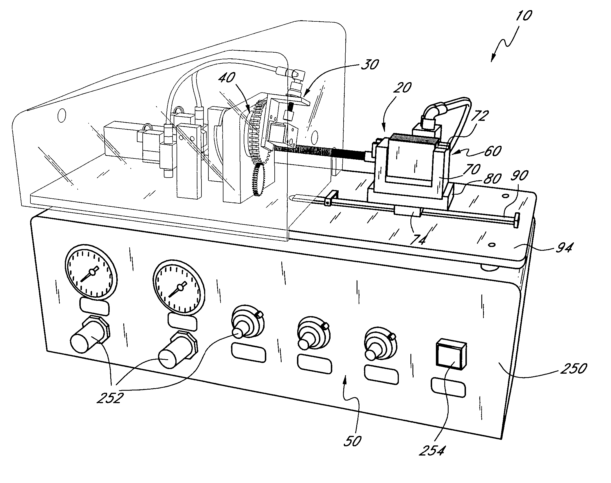
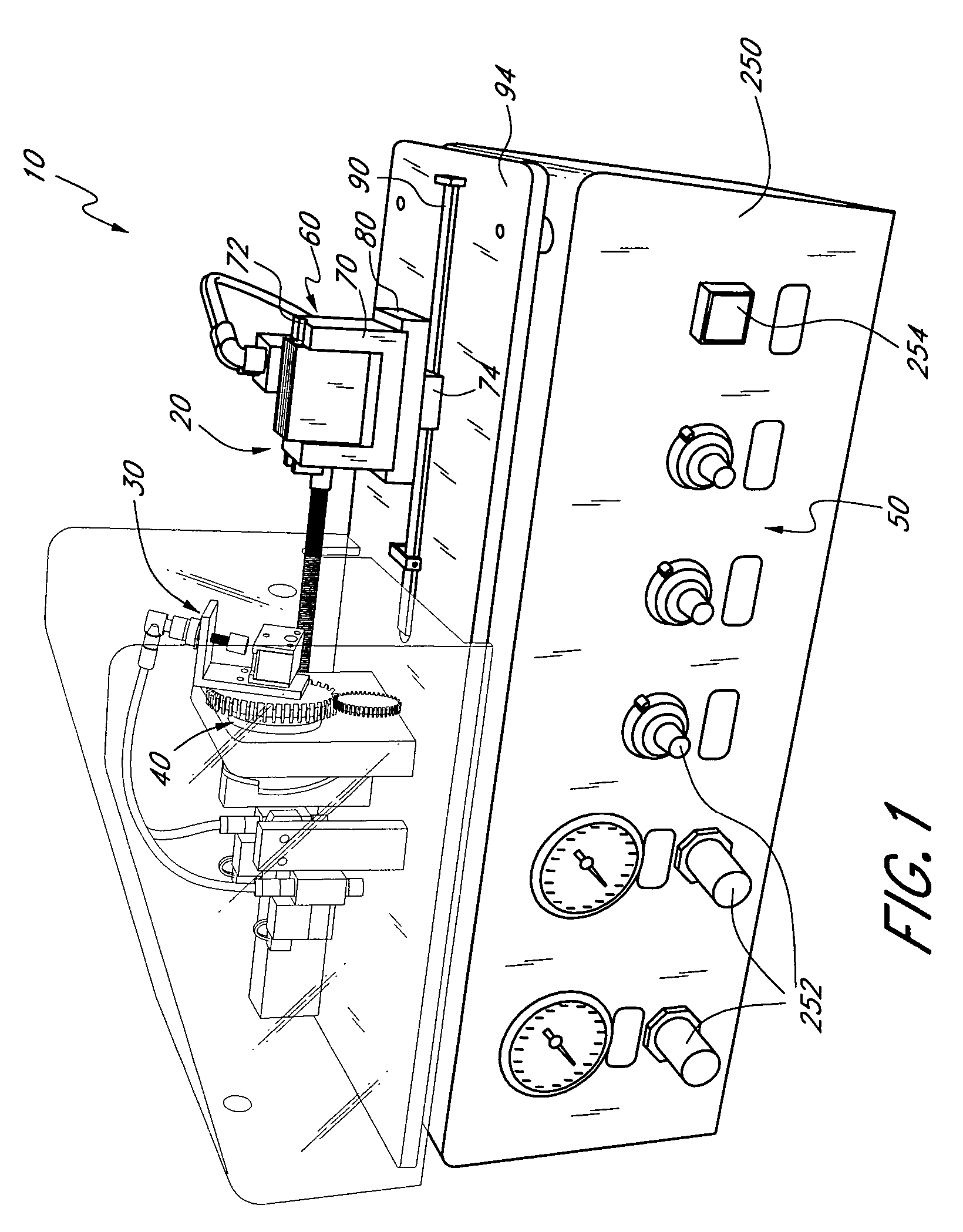
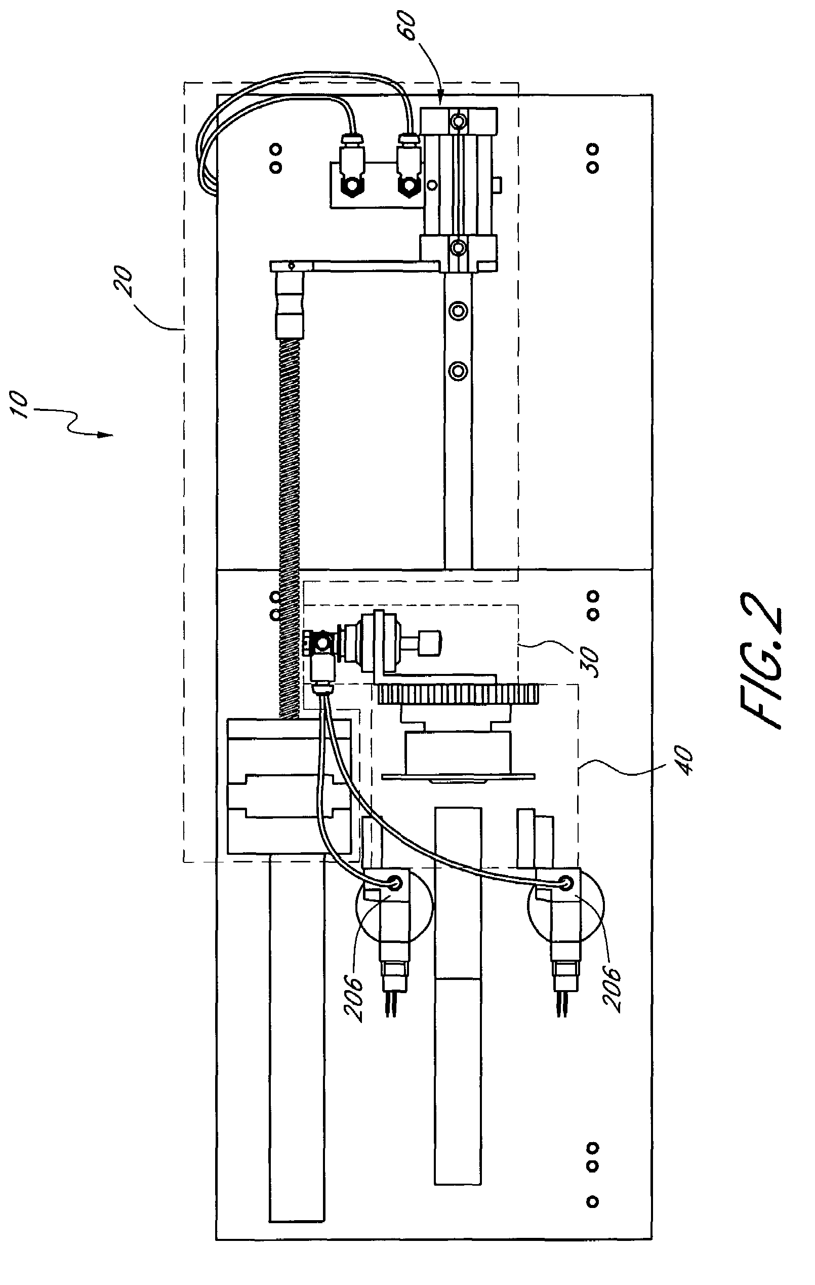
[0008]According to one preferred embodiment, a swaging machine is configured to swage a marker band onto a catheter and comprises a feed system comprising a motor and a clamp, the clamp slideably disposed on a rail. The motor is in driving engagement with the clamp and configured for transmitting a feeding force to the clamp. An impact system comprises a hammer and a die. The hammer is configured to deliver an impact to the die, and the die is configured to distribute the impact force as a swaging force to the marker band. In addition, a rotation system comprises a motor and is configured to rotate the impact system to distribute the swaging force about the circumference of the marker band. Moreover, the motor can be operatively coupled to a feed screw, the feed screw having a coupled end connected to the clamp and the motor can be configured to drive the feed screw and the clamp linearly. A damping coupling can optionally be provided between the feed screw and the clamp. In additio...


PUM

PropertyMeasurementUnit
outer diameteraaaaaaaaaa
outer diametersaaaaaaaaaa

Abstract

A swaging machine is configured to substantially uniformly reduce the diameter of a tubular attachment, such as a marker band, to result in a smooth and repeatable finished part. The swaging machine comprises a feed system, an impact system, and a rotation system. A split die having a compound die cavity is provided for use in conjunction with the swaging machine to receive an impact force from the impact system and, in turn, apply a swaging force to the marker band. The rotation system rotates the impact system, including the die, about the axis of the marker band to apply swaging forces about the circumference of the marker band, while the feed system feeds the marker band through the die thereby applying swaging forces along the length of the marker band.

Description

CROSS REFERENCE TO RELATED APPLICATIONS[0001]The current application claims priority to Provisional Patent Application having Ser. No. 60 / 444,999 filed Feb. 4, 2003, the entirety of which is hereby incorporated by reference.BACKGROUND OF THE INVENTION[0002]1. Field of the Invention[0003]Embodiments of the present invention relate to the field of swaging marker bands and joining sleeves to hollow tubing, solid wire or a rod. More specifically, the swaging machine of the preferred embodiments applies a repeating impact to reduce the diameter of a cylindrical marker band.[0004]2. Description of the Related Art[0005]When using catheters, operators desire to visualize the precise location of the catheter within a patient's body. Therefore, catheters are often configured with marker bands, which are x-ray opaque indicators that allow an operator to see the specific location of the marker band through x-ray imaging. These marker bands are typically swaged onto the catheter.[0006]Swaging is...

Claims


Application Information

Patent Timeline
Patent Type & Authority Patents(United States)
IPC IPC(8): B21D39/04
CPCB21D39/04B21D39/042Y10T29/53996
Inventor STUPECKY, JOSEF J.
Owner CONFLUENT MEDICAL TECH INC
Why Eureka
Try Eureka